
Systems and methods for cancelling interference using multiple attenuation delays

a technology of attenuation delay and interference cancelling, which is applied in the direction of transmission control/equalisation, radio transmission, electrical equipment, etc., can solve the problems of system ineffective receiving the desired signal and the challenge of reducing the self-interference signal in the full-duplex wireless communication system, and achieve the effect of reducing the self-interference signal

Active Publication Date: 2013-11-14
THE BOARD OF TRUSTEES OF THE LELAND STANFORD JUNIOR UNIV
View PDF6 Cites 120 Cited by
  • Summary
  • Abstract
  • Description
  • Claims
  • Application Information

AI Technical Summary

Benefits of technology

The present invention relates to a wireless communication device that includes a cancelation circuit for reducing self-interference signals. The cancelation circuit includes a control block, N delay paths, a combiner, a subtractor, and an isolator. The delay paths include a control block, variable attenuators, and a splitter. The method of cancellation involves receiving a sample of the transmit signal, generating delayed versions of the sample, attenuating the delayed versions, combining the delayed versions, and subtracting the combined signal from the received signal. The invention can effectively cancel out self-interference signals and improve the quality of wireless communication.

Problems solved by technology

Using the same frequency for simultaneous transmission and reception in a conventional wireless system results in significant amount of self-interference at the receiver thereby rendering the system ineffective in receiving the desired signal.
Reducing the self-interference signal in a full duplex wireless communication system remains a challenge.

Method used


Image

  • Systems and methods for cancelling interference using multiple attenuation delays
  • Systems and methods for cancelling interference using multiple attenuation delays
  • Systems and methods for cancelling interference using multiple attenuation delays

Examples


Embodiment Construction

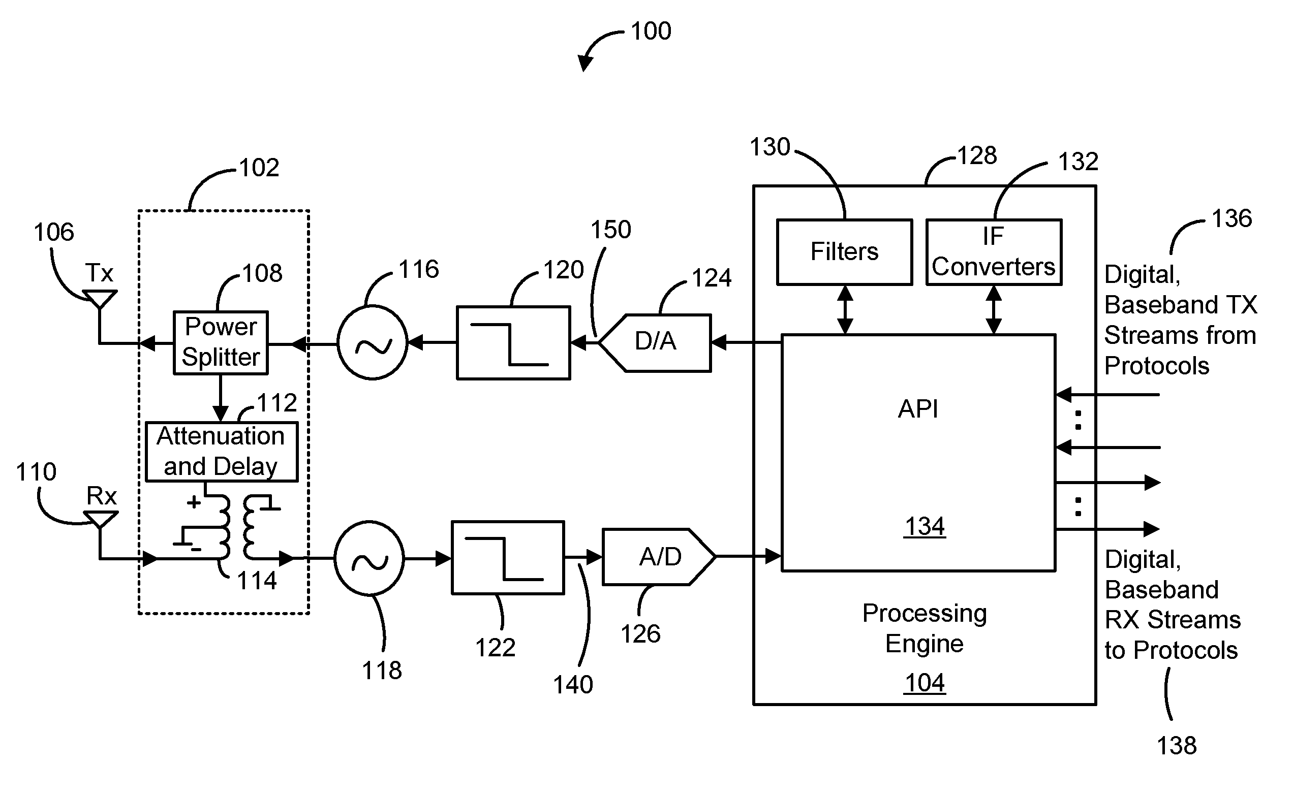
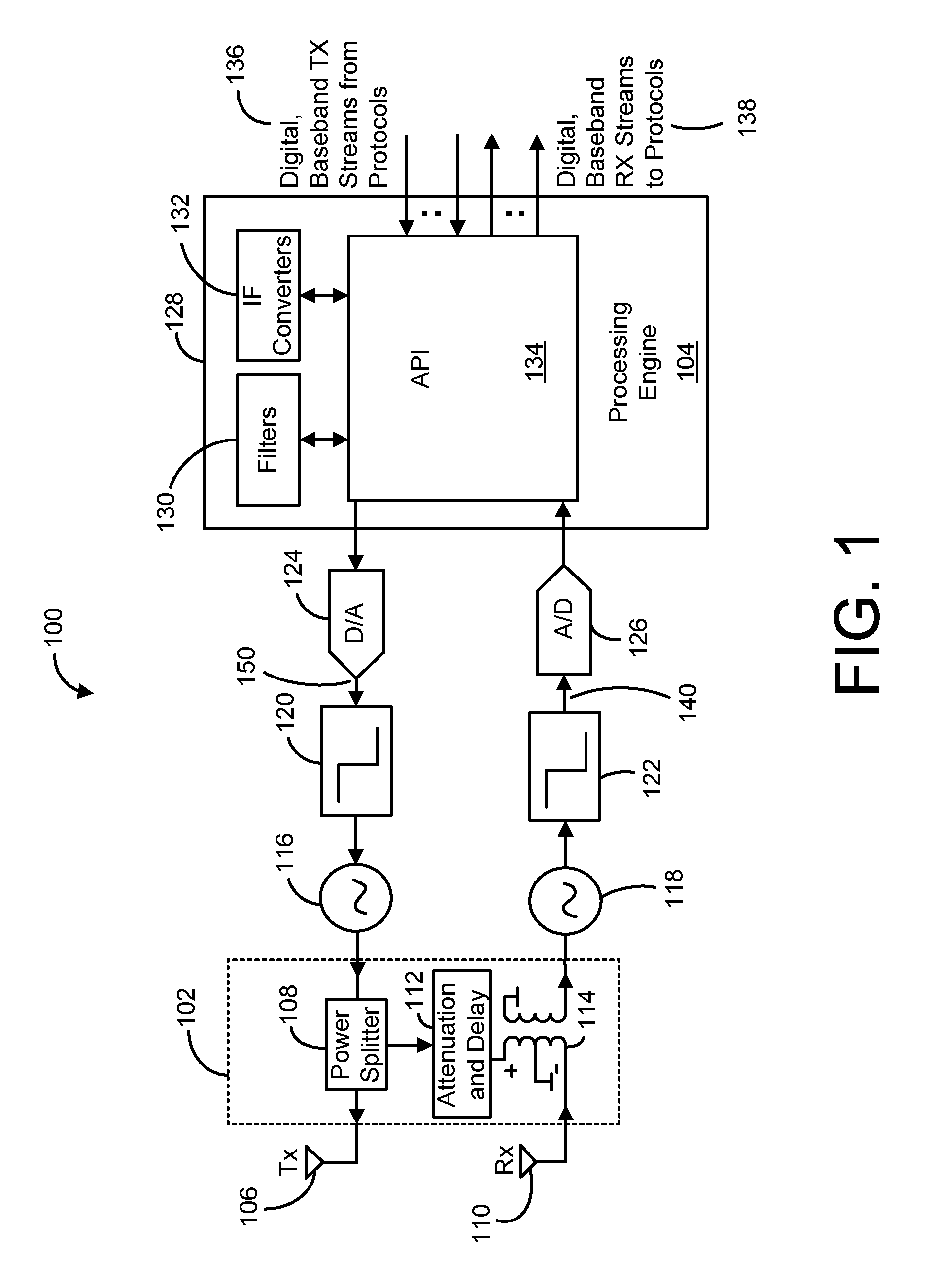
[0025]FIG. 1 is a simplified block diagram of a full-duplex wireless communication device 100, in accordance with one embodiment of the present invention. Wireless communication device 100, which may be a cellular phone, a base station, an access point or the like, is configured to transmit data / signals via a downlink and receive data / signals via an uplink. Wireless communication device (herein alternatively referred to as device) 100 is shown, as including, in part, a digital-to-analog converter (DAC) 122, a filter 120, a frequency upconverter 116, and a transmit antenna 106 disposed in the transmit path 150. Device 100 is further shown as including, in part, a receive antenna 110, a frequency down converter 118, a filter 122, and an analog-to-digital converter (ADC) 126 disposed in the receive path 140. Device 100 is also shown as including a processing engine 104, and a self-cancellation circuit 102. Processing engine 104 is configured to control / process various operations as des...


PUM


Abstract

A wireless communication device includes, in part, at least one antenna for receiving or transmitting a signal, and a cancelation circuit adapted to cancel or reduce the self-interference signal. The cancelation circuit includes, in part, a control block, N delay and attenuation paths, a combiner, and a subtractor. Each path includes a delay element and a variable attenuator whose attenuation level varies in response to a control signal generated by the control block. Each path receives a sample of the transmit signal and generates a delayed and attenuated (weighted) version of the sample signal. The combiner combines the N delayed and weighted versions of the sample signal to construct a signal representative of the self-interference signal. The subtractor subtracts the constructed signal from the received signal thereby the cancel or reduce the self-interference signal therefrom.

Description

CROSS-REFERENCES TO RELATED APPLICATIONS[0001]The present application claims priority to U.S. Provisional Patent Application No. 61 / 657,567, filed Jun. 8, 2012, and entitled “Multiple Tap Feed Forward Cancellation,” and is a continuation-in-part of U.S. patent application Ser. No. 13 / 762,043, filed Feb. 7, 2013, and entitled “Systems and Methods for Full-Duplex Signal Shaping,” which claims priority to U.S. Provisional Patent Application No. 61 / 596,628, filed Feb. 8, 2012, and entitled “Enabling Algorithms and RF Circuitry for Full-duplex Communication Over Arbitrary Spectrum Fragments,” the contents of all of which are incorporated herein by reference in their entirety.FIELD OF THE INVENTION[0002]The present invention relates to wireless communication systems, and more particularly to cancellation or reduction of self-interference in full-duplex communication systems.BACKGROUND[0003]A wireless communication system operating in a half-duplex mode may use the same frequency to either...

Claims


Application Information

Patent Timeline
IPC IPC(8): H04B1/56
CPCH04B1/56H04B1/126H04B1/525
Inventor HONG, STEVENMEHLMAN, JEFFBHARADIA, DINESHKATTI, SACHIN
Owner THE BOARD OF TRUSTEES OF THE LELAND STANFORD JUNIOR UNIV
Learn More