

System and method for treatment of non-ventilating middle ear by providing a gas pathway through the nasopharynx
- Summary
- Abstract
- Description
- Claims
- Application Information
AI Technical Summary
Benefits of technology
Problems solved by technology
Method used
Image

Examples
Embodiment Construction
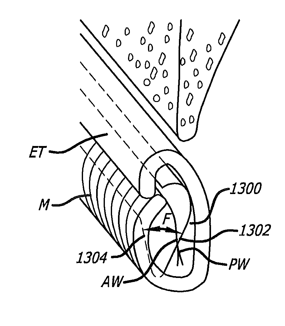
[0047]The embodiments of the present invention are directed toward methods and systems for accessing, diagnosing and treating target tissue regions within the middle ear and the Eustachian tube.
[0048]Access
[0049]One embodiment of the present invention is directed toward using minimally invasive techniques to gain trans-Eustachian tube access to the middle ear. A middle ear space may be accessed via a Eustachian tube (ET). To obtain this access to the Eustachian tube orifice, a guide catheter having a bend on its distal tip greater than about 30 degrees and less than about 90 degrees may be used. Once accessed, diagnostic or interventional devices may be introduced into the Eustachian tube. Optionally, to prevent damage to the delicate middle ear structures, a safety mechanism may be employed. In one embodiment, the safety mechanism may include a probe and / or a sensor introduced into the middle ear via the tympanic membrane as shown in FIG. 7. For example, the probe may be an endosco...
PUM
 Abstract
Description
Claims
Application Information