Rotor for electric machine

a rotary electric machine and rotor technology, applied in the direction of dynamo-electric machines, magnetic circuit rotating parts, magnetic circuit shape/form/construction, etc., can solve the problem of low torque of rotary electric machines, and achieve the effect of enhancing torque and increasing the magnetic flux in the magnetic pol

Active Publication Date: 2013-11-21
TOYOTA JIDOSHA KK +2
View PDF3 Cites 45 Cited by
  • Summary
  • Abstract
  • Description
  • Claims
  • Application Information

AI Technical Summary

Benefits of technology

[0034]The rotor for a rotary electric machine according to the invention allows securing a wide magnetic path region that is formed between the first permanent magnet and the second permanent magnets. This allows easing, as a result, magnetic saturation in the magnetic path region. In addition, flow of magnetic flux is suppressed by the magnetic flux suppression hole, which allows suppressing leaks of magnetic flux from the first permanent magnet towards the inner periphery of the magnetic pole, while the magnetic flux from the second permanent magnets is caused to flow effectively towards the outer peripheral face of the magnetic pole through the magnetic path region. The magnet magnetic flux in the magnetic pole can therefore be further increased. The rotor for a rotary electric machine according to the invention as described above allows enhancing the torque in a rotary electric machine that is equipped with the above-described rotor.

Problems solved by technology

In turn, this can result in a lower torque of the rotary electric machine.

Method used


Image

  • Rotor for electric machine
  • Rotor for electric machine
  • Rotor for electric machine

Examples


Embodiment Construction

[0045]Embodiments of the invention are explained below with reference to accompanying drawings. In the explanation below, specific forms, materials, numerical values, directions and so forth are merely examples for facilitating comprehension of the invention, and can be appropriately modified depending on the intended application, purpose, specifications and the like.

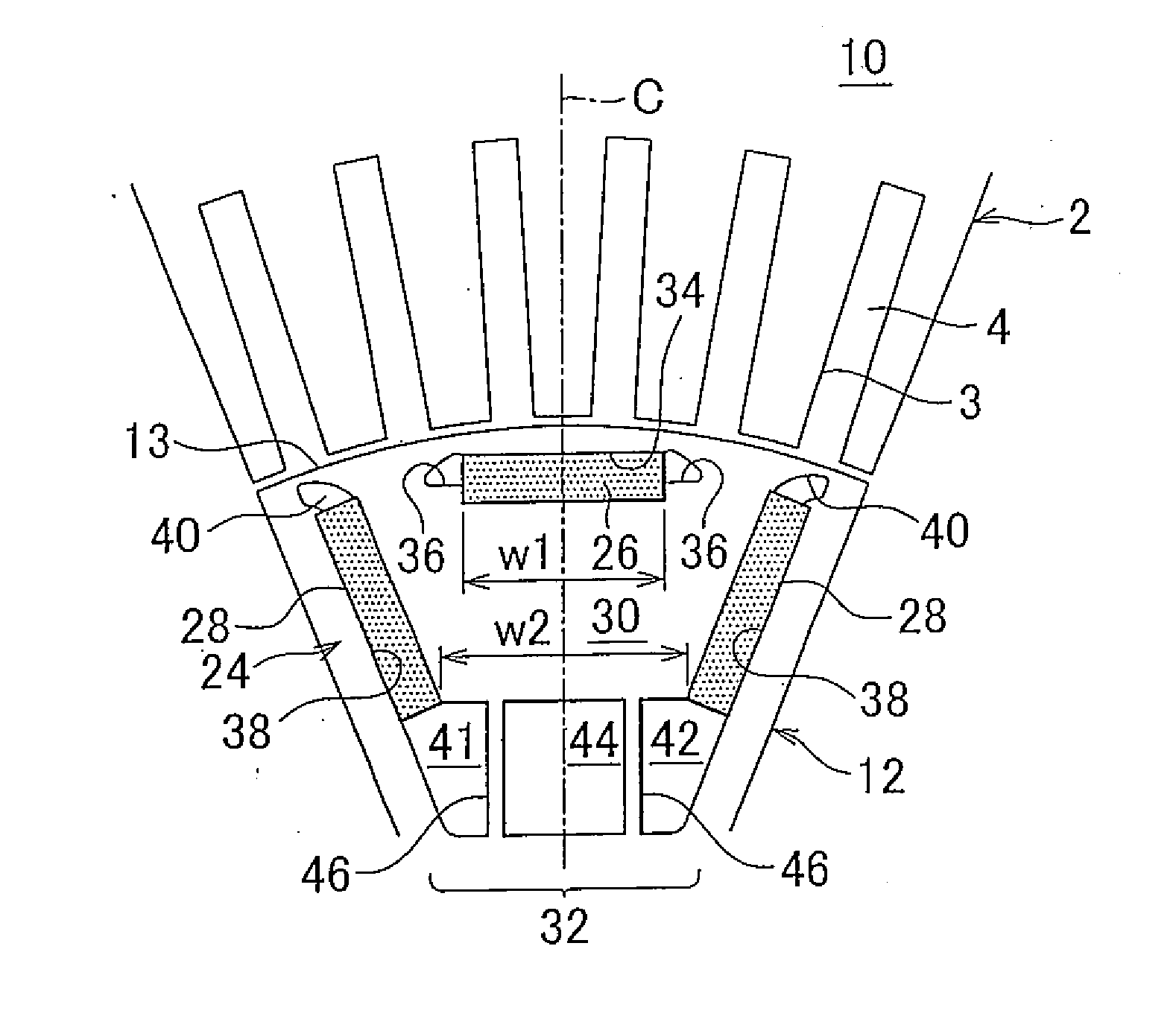
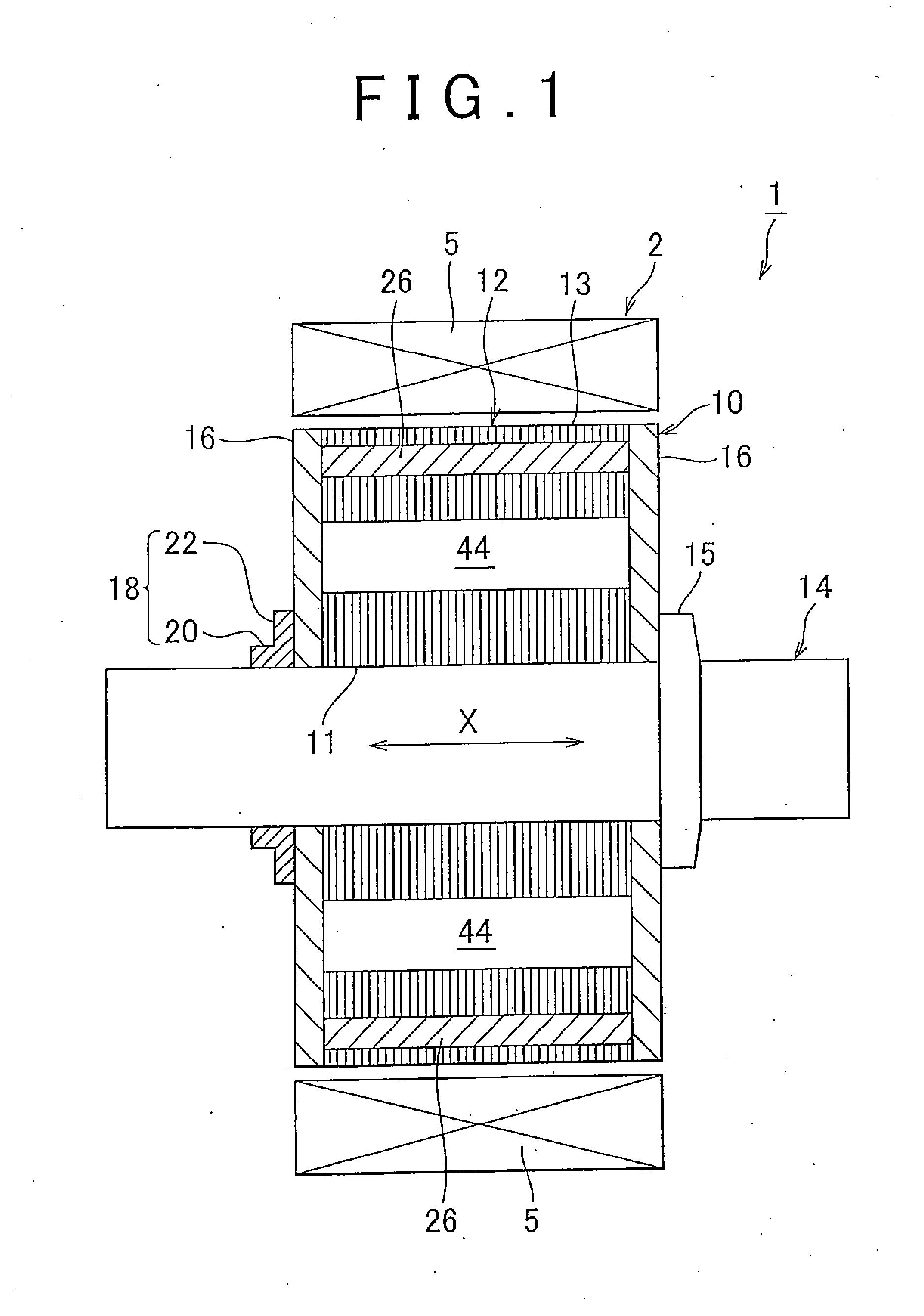
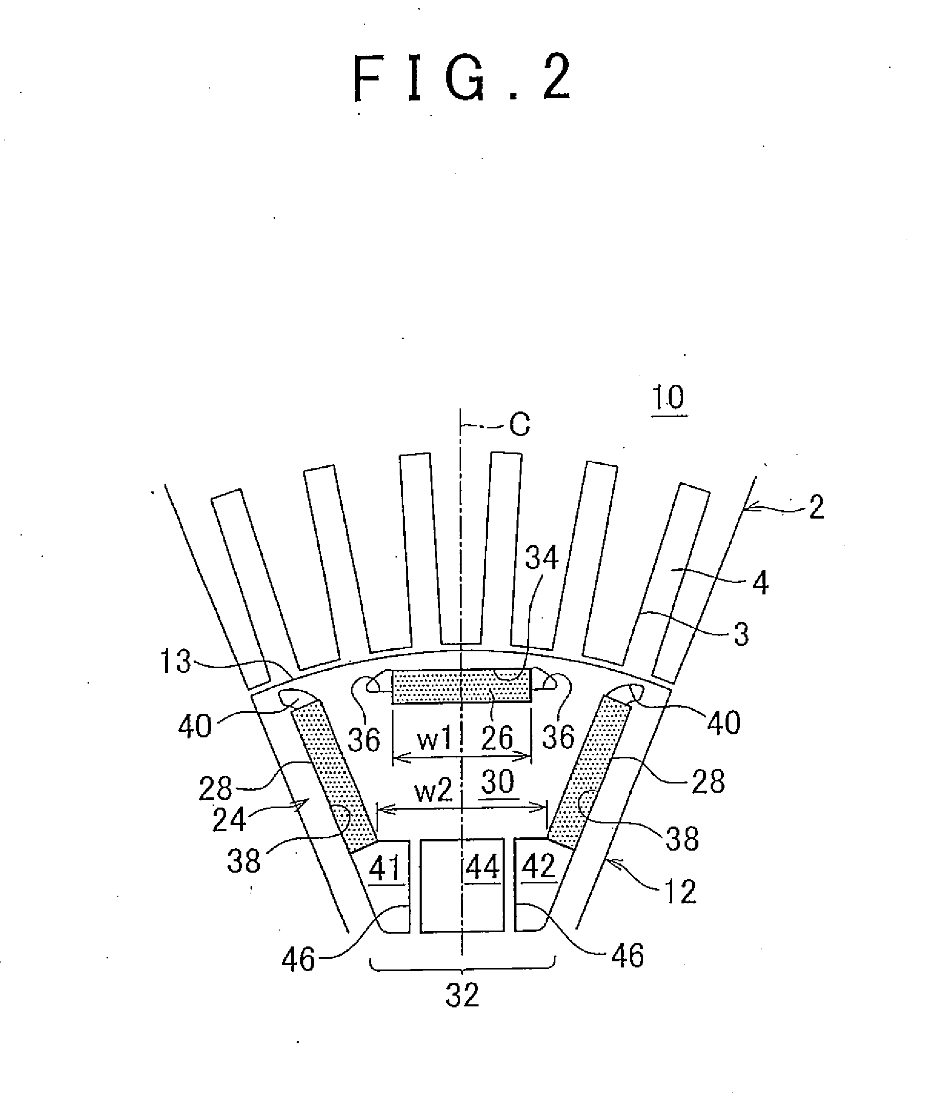
[0046]FIG. 1 illustrates a longitudinal section along the axial direction of a rotary electric machine 1 provided with a rotor 10 of the embodiment. FIG. 2 illustrates an enlarged view of one magnetic pole of the rotor 10 together with part of a stator 2.

[0047]The rotary electric machine 1 has a tubular stator 2 and a rotor 10 that is rotatably provided inside the stator 2. A plurality of teeth 3 that point inward in a radial direction is provided, at equal spacings in the circumferential direction, on the inner periphery of the stator 2. Slots 4 are respectively formed, in a number identical to that of the teeth 3, bet...


PUM


Abstract

A rotor (10) for a rotary electric machine has a plurality of magnetic poles (24) provided at intervals, in a circumferential direction, at the outer periphery of a rotor core (12). Each of the magnetic poles (24) has a first permanent magnet (26) buried in the center of the magnetic pole, and a pair of second permanent magnets (28) that are buried on both sides of the first permanent magnet (26) in the circumferential direction, and that are disposed such that a mutual spacing between the pair of the second permanent magnets (28) becomes narrower inward in the radial direction. A narrowest spacing between the pair of second permanent magnets (28) is set to be wider than a longitudinal-direction width of the first permanent magnet (26) in a magnetic path region (30) that is defined by the first permanent magnet (26) and the pair of second permanent magnets (28).

Description

BACKGROUND OF THE INVENTION[0001]1. Field of the Invention[0002]The invention relates to a rotor for a rotary electric machine, and more particularly to a rotor for a rotary electric machine in which a plurality of magnetic poles are disposed at intervals, in a circumferential direction, at an outer periphery of a rotor core.[0003]2. Description of Related Art[0004]For example, Japanese Patent Application Publication No. 2008-306849 (JP-A-2008-306849) discloses a rotary electric machine that has a stator in which a stator coil is distributedly wound around an inner periphery portion, and a buried permanent magnet-type rotor that is rotatably provided in the stator. The above rotor is made up of a rotary shaft and a cylindrical core body that is fixed to the rotary shaft.[0005]The above core body results from integrally constructing, by crimping or the like, an axial-direction stack of magnetic steel sheets, each formed through punching, into a circular ring-like shape. A plurality o...

Claims


Application Information

Patent Timeline
Patent Type & Authority Applications(United States)
IPC IPC(8): H02K1/27
CPCH02K1/27H02K1/2766
Inventor SANO, SHINYATAKEDA, KENINAGAKI, TOMOHIROOTAKE, SHINICHIMIYAJI, TSUYOSHIWATANABE, YUTAUTAKA, RYOSUKE
Owner TOYOTA JIDOSHA KK
Why Eureka
Try Eureka