Shaft attachment means for high efficiency permanent magnet machine with separated tab pole rotor

Active Publication Date: 2013-11-21
LC ADVANCED MOTOR TECH CORP
View PDF6 Cites 7 Cited by
  • Summary
  • Abstract
  • Description
  • Claims
  • Application Information

AI Technical Summary

Benefits of technology

[0007]An important feature of the invention resides in the provision of magnetic

Problems solved by technology

In addition, it is advantageous to provide a means of holding each magnet section to each other in low flux density regions b

Method used


Image

  • Shaft attachment means for high efficiency permanent magnet machine with separated tab pole rotor
  • Shaft attachment means for high efficiency permanent magnet machine with separated tab pole rotor
  • Shaft attachment means for high efficiency permanent magnet machine with separated tab pole rotor

Examples


Embodiment Construction

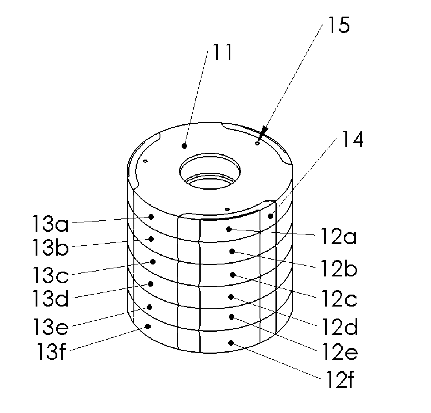
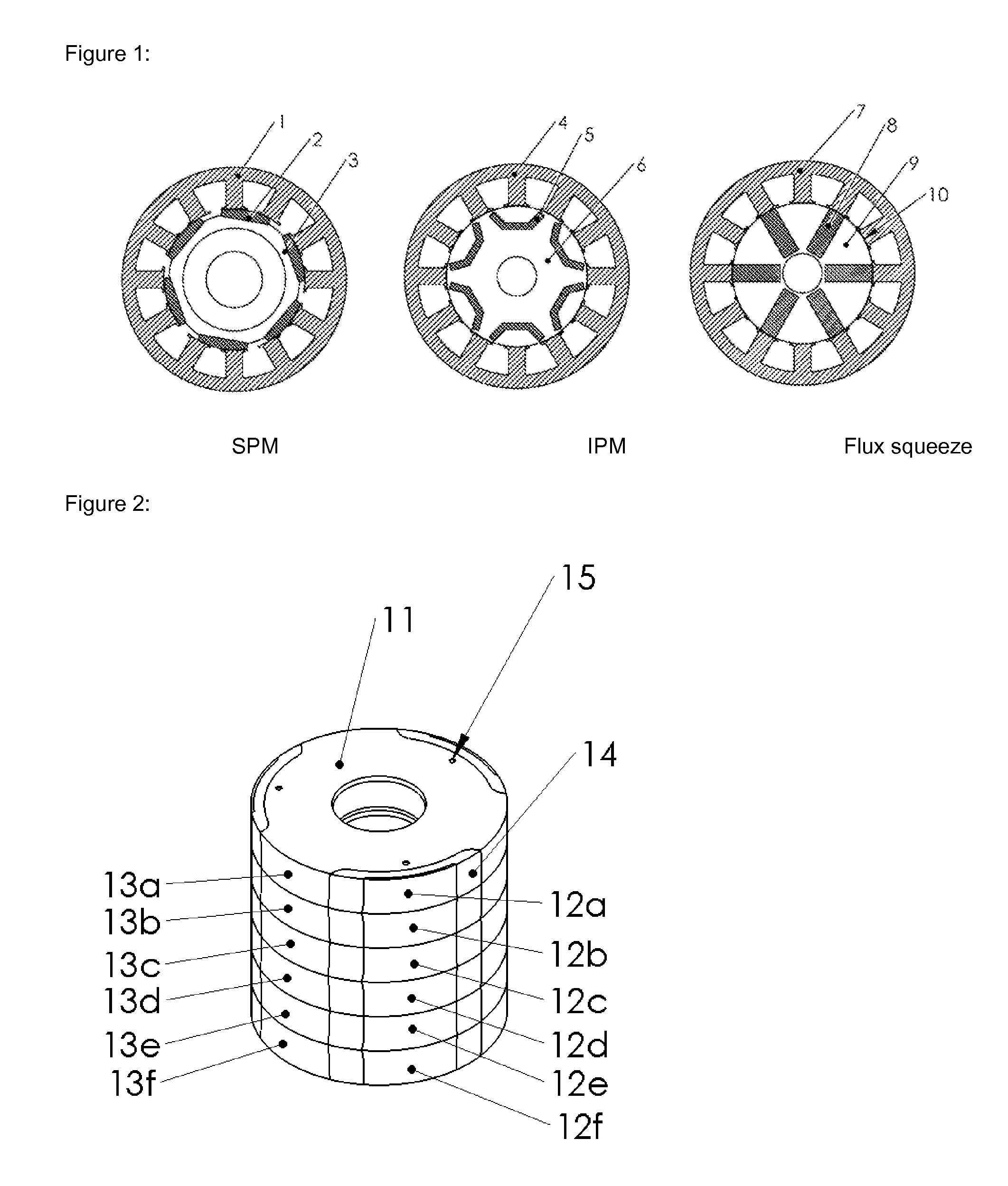
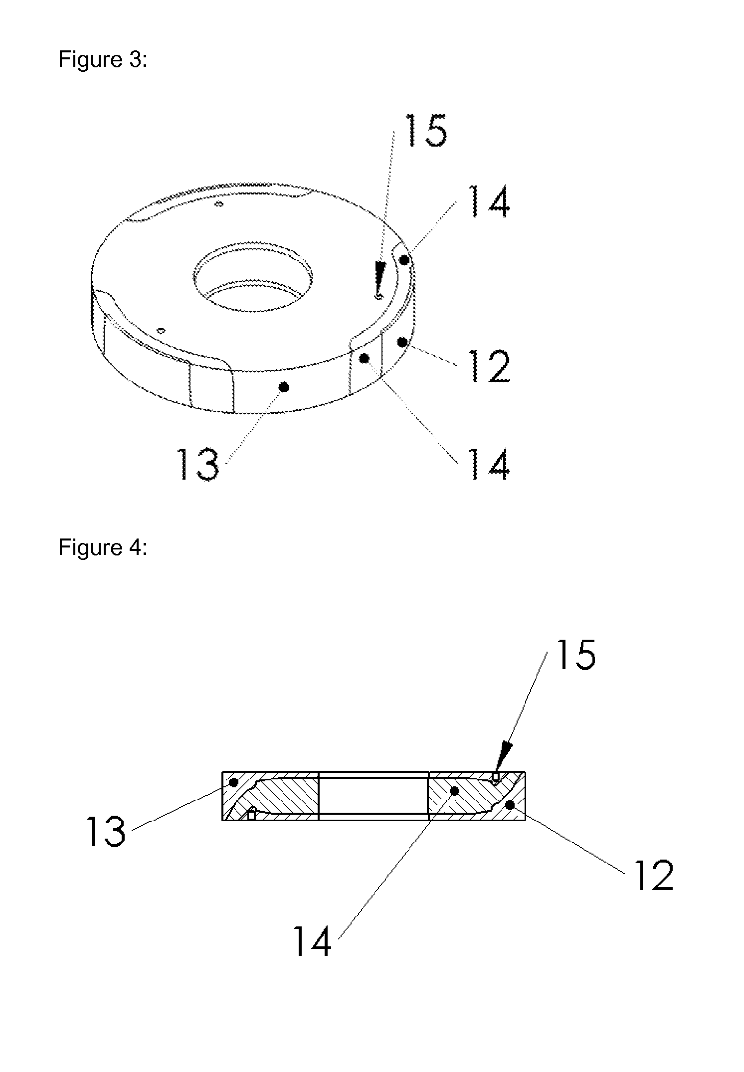
[0024]Referring particularly to FIG. 2, a stack of six (6) magnet assemblies or sections 11 is shown in a six pole configuration. Each section has three north poles 12a-12f and three south poles 13a-13f respectively located on tabs extending from opposite pole plates 12 and 13, FIG. 4. Ceramic magnet 14 is disposed between the pole plates 12 and 13 and through openings 15,15 are provided in areas of low flux density. Tabs of the same polarity are aligned axially with each other as shown in FIG. 2 with tabs 12a-12f aligned axially and tabs 13a-13f similarly aligned.

[0025]The ceramic magnet per se is best shown in FIG. 5 and has a center region 17 that is magnetized similar to a speaker magnet with north and south poles on opposite generally planar faces. Circumaxially spaced pole separation regions or separators 16,16 may be integral with the magnet or may be separate parts. They are magnetized orthogonal to the center region 17 with the magnetizing direction extending arcuately betw...


PUM


Abstract

A permanent magnet motor, generator or the like that uses ceramic magnets in the rotor to concentrate the magnetic flux in the airgap. Magnet poles are formed by pole plates with tabs forming north and south poles with magnetic separators therebetween. Magnet sections are stacked axially. Connection to the shaft is made by means of a collet or other attachment method.

Description

BACKGROUND OF THE INVENTION[0001]Rotary electric machines including electric motors, generators, and the like have employed permanent magnets for some time. These machines take on many different topologies, the two most common topologies that use internal rotors being “Surface Permanent Magnet—SPM” and “Interior Permanent Magnet—IPM.” Additionally there is a topology “Interior PM—flux squeeze” that is also shown in the prior art. These topologies can be seen in the following patents and applications incorporated herein by reference:U.S. Pat. App. No.2007 / 0057589shows IPMU.S. Pat. No.7,362,025shows IPMU.S. Pat. No.6,703,746shows IPMU.S. Pat. App. No.2009 / 0134731shows SPMU.S. Pat. No.7,486,037shows SPMU.S. Pat. No.3,072,813shows Interior PM-flux squeezeU.S. Pat. No.7,148,598shows Interior PM-flux squeeze[0002]Generally high efficiency motors and generators use rare earth magnets that contain Neodymium (Nd) and Dysprosium (Dy) which are both expensive and which may be limited in supply...

Claims


Application Information

Patent Timeline
IPC IPC(8): H02K1/27H02K1/28
CPCH02K1/2713H02K1/28H02K1/2773H02K1/30H02K15/03H02K21/24
Inventor MARVIN, RUSSEL HUGHSHEPHERD, NIGEL
Owner LC ADVANCED MOTOR TECH CORP
Why Eureka
Try Eureka