Ceramic heater and gas sensor element

Active Publication Date: 2013-02-28
DENSO CORP
View PDF8 Cites 19 Cited by
  • Summary
  • Abstract
  • Description
  • Claims
  • Application Information

AI Technical Summary

Benefits of technology

[0013]The present invention has been achieved in light of the above-described issues. An object of the present invention is

Problems solved by technology

However, the above-mentioned ceramic heater has the fallowing issues.
Therefore, when, conducting electricity to the ceramic heater, stress is likely to be imposed on the joint between the heating element and the lead portion due to the difference in linear expansion between, the heating element and the lead portion, causing cracks starting from the joint.
As the gas sensor element, is more required to warm up rapidly (early-activation) and to be used under high, temperature, this issue becomes more

Method used


Image

  • Ceramic heater and gas sensor element
  • Ceramic heater and gas sensor element
  • Ceramic heater and gas sensor element

Examples


Example

Example 1

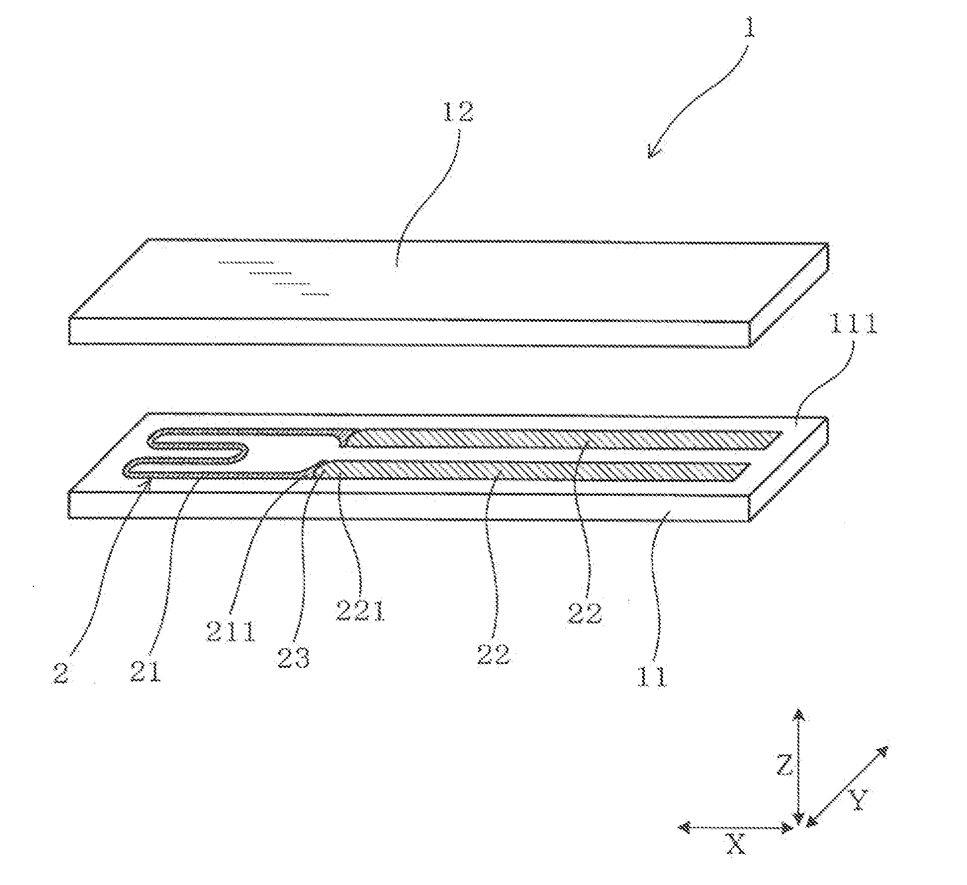
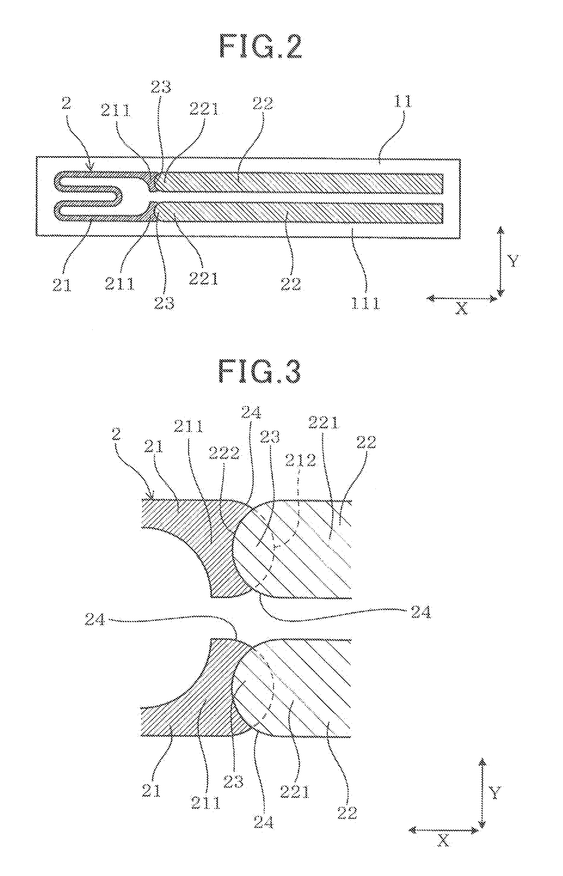
[0061]A ceramic heater and a gas sensor element according to an example 1 are described with reference to the drawings. As shown in FIGS. 1 to 4, a ceramic heater 1 according to the example 1 has a ceramic substrate 11 and a heater pattern 2 formed on the ceramic substrate 11. The heater pattern 2 includes a heating element 21 that generates heat when a current is passed therethrough and a pair of lead portions 22 that conducts electricity to the heating element 21.

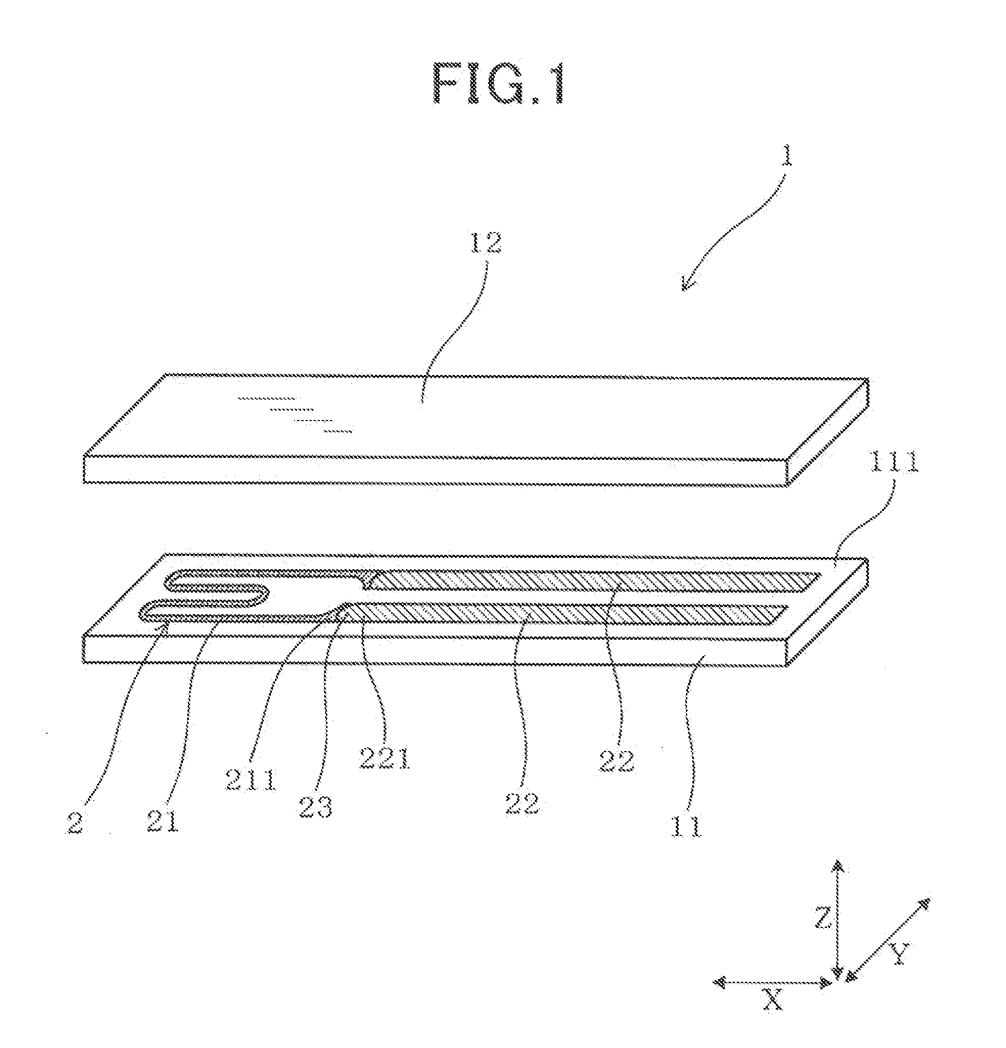
[0062]The heating element 21 has a pair of heating connection ends 211 connected to the pair of lead, portions 22, The pair of lead portions 22 has lead connection ends 221 connected to the pair of heating connection ends 211 of the heating element 21. The heating element 21 and the lead portions 22 are connected at joints 23. The joints 23 are formed by overlaying the heating connection ends 211 and the lead connection ends 211.

[0063]The heater pattern 2 formed on the ceramic substrate 11 as viewed from a direct...

Example

Example 2

[0106]A ceramic heater 1 according to a second example is described with reference to the FIGS. 7 to 9. In the second and the subsequent examples, the components identical with or similar to those in the first example are given, the same reference numerals for the sake of omitting unnecessary explanation.

[0107]The second example is different from the first example in that the structure of the heating element 21 and the lead portions 22 in the heater pattern 2 has been changed.

[0108]In the example of the heater pattern 2 shown in FIG. 7, the heating connection end 211 of the heating element 21 has the edge 212 having an arc-shaped curve. On the other hand, the lead connection end 221 of the lead portion 22 has the edge 222 which is straight and parallel to the width direction Y.

[0109]In the example of the heater pattern 2 shown in FIG. 8, the heating connection end 211 of the heating element 21 has the edge 212 which is straight and parallel to the width direction Y. On the ...

Example

Example 3

[0113]The ceramic heater 1 according to a third example is described with reference to FIG. 11.

[0114]The third example is different from the first example in that the structure of the heating element 21 and the lead portions 22 in the heater pattern 2 has been changed from the first example.

[0115]As shown in FIG. 11, the heating connection end 211 of the heating element 21 has the edge 212 having a convex part 213 which projects from the edge 212 in the long direction X. The convex part 213 is formed so as to project from substantially the center, in the width direction Y, of the edge 212 of the heating connection end 211.

[0116]The lead connection end 221 of the lead portion 22 has the edge 222 having a convex part 223 which is configured similar to the convex part 213.

[0117]When the convex parts 213, 223 have a length S (S1, S2) in the long direction X and each of the joints 23 excluding the convex parts 213, 223 has a length M in the long direction X, the relation of S=a×...


PUM


Abstract

A ceramic heater in which a heater pattern is formed on a ceramic substrate is disclosed. The heater pattern has a heating element and lead portions. The heating element has heating connection ends and the lead portions have lead connection ends. The heating element and the lead portions are connected at joints which are formed by overlaying the heating connection ends and the lead connection ends. The heater pattern, as viewed in a direction perpendicular to a plane in which the heater pattern is formed, has inwardly recessed concavities formed on both width wise sides of each of the joints. The concavities include portions in each of which a profile of the respective heating connection end crosses a profile of the respective lead connection end.

Description

CROSS REFERENCE TO RELATED APPLICATION[0001]This application is based upon and claims the benefit of priority from the prior Japanese Patent Application No. 2011-187367, filed Aug. 30, 2011, the entire content of which is incorporated herein by reference.BACKGROUND OF THE INVENTION[0002]1. Field of the Invention[0003]The present invention relates to a gas sensor element and a ceramic heater to heat the gas sensor element.[0004]2. Description of the Related Art[0005]A gas sensor is provided in an exhaust gas system of a vehicle internal combustion engine. The gas sensor detects a concentration of a specific gas contained in a gas to be measured such as an exhaust gas. The gas sensor has a built-in ceramic heater for heating a gas sensor element.[0006]For example, there is a ceramic heater having a heater pattern formed on a surface of a ceramic substrate. The heater pattern has a heating element that generates heat when a current is passed therethrough and a lead portion that conduct...

Claims


Application Information

Patent Timeline
IPC IPC(8): H05B3/10
CPCH05B3/06H05B3/12H05B3/265G01N27/407H05B2203/013G01N27/4067H05B2203/003
Inventor SATOU, CHIMATO
Owner DENSO CORP
Why Eureka
Try Eureka