Electrical connector with flame-resistant inserts

Active Publication Date: 2014-03-27
SOURIAU
View PDF2 Cites 2 Cited by
  • Summary
  • Abstract
  • Description
  • Claims
  • Application Information

AI Technical Summary

Benefits of technology

[0015]This connector is characterized by the fact that the insert has a protection element placed between the front part and the rear part and made of a flame-insensitive material capable, under the effect of high temperature, of maintai

Problems solved by technology

However, a thermoplastic insert subjected to a flame or to a high temperature close to its melting temperature will tend to soften or even to melt.
The electrical contacts will then no longer be electrically insulated from one another, and this can generate short-circuits within the connector and lead to damage to the insulation connected to this connector.
It can thus be understood that it is difficult to use connectors with thermoplastic inserts in flame-hazard environments such as motor environments especially when the si

Method used


Image

  • Electrical connector with flame-resistant inserts
  • Electrical connector with flame-resistant inserts

Examples


Example

[0027]The description pertains to an electrical connector, the insert of which is capable of at least partially withstanding flames or high room temperature. In addition, this electrical connector has environment-friendly properties enabling it to be easily recycled.

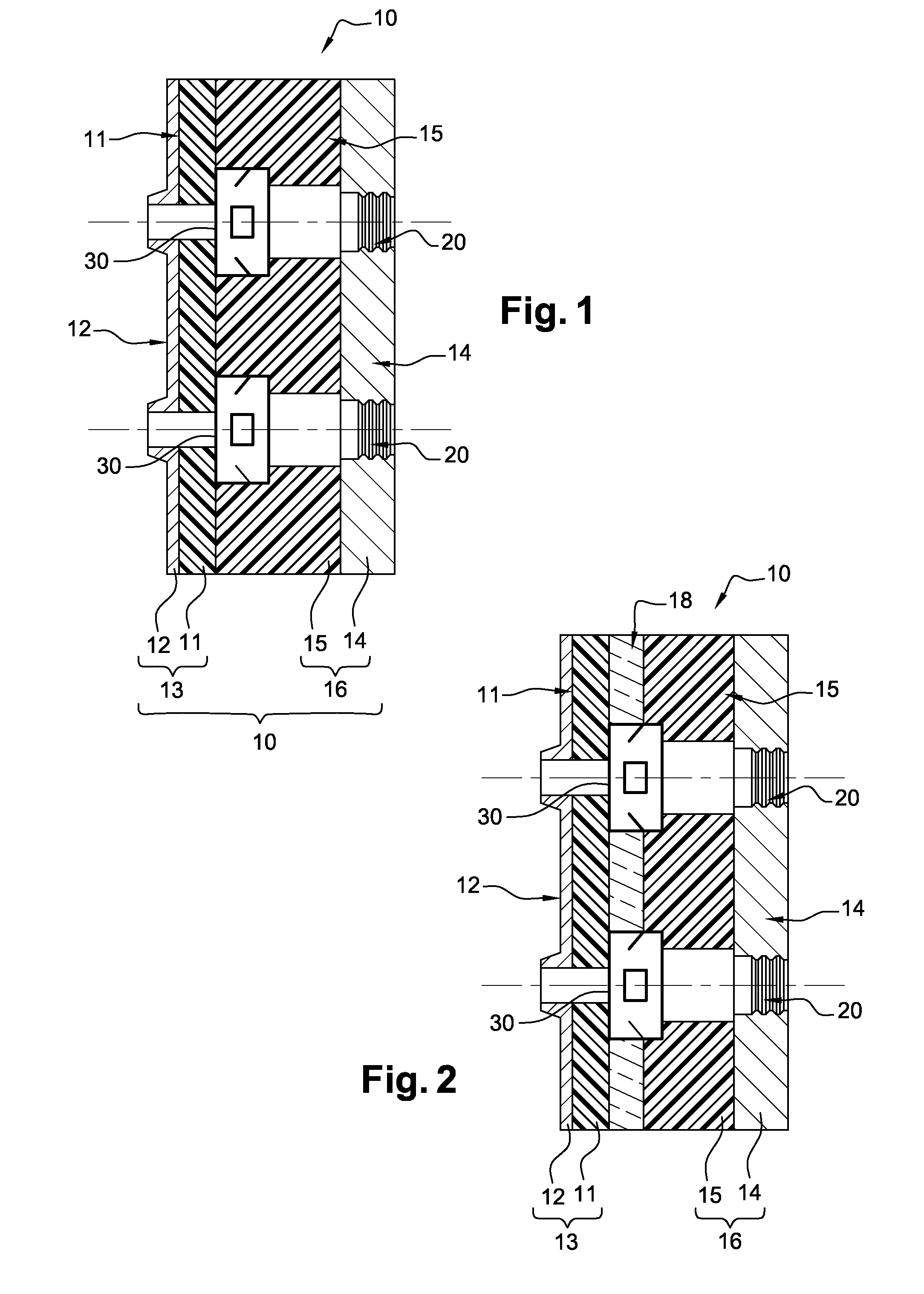
[0028]To this end, the connector of the invention comprises a two-part insert provided with a protection element made out of a flame-insensitive material. An example of a connector according to the invention is shown in FIG. 2.

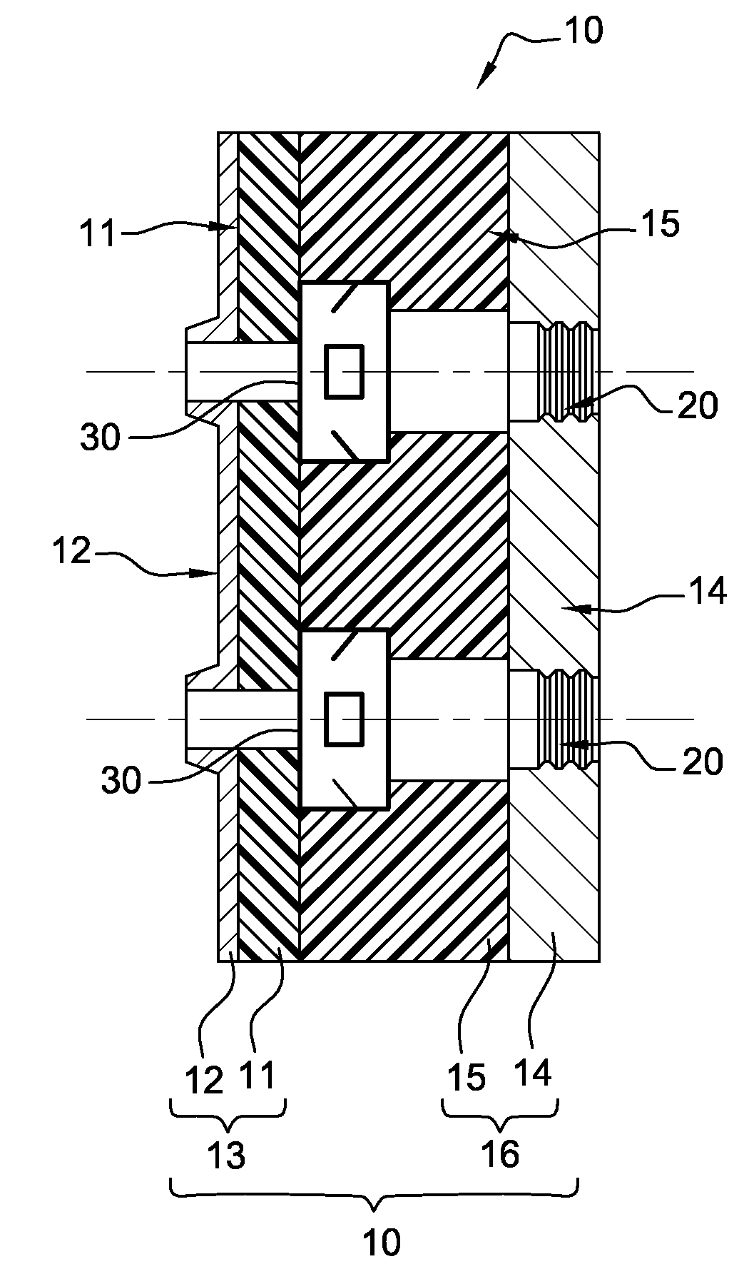
[0029]This connector has an insert 10 crossed by longitudinal cavities 20 each capable of housing an electrical contact 30.

[0030]This insert 10 has a front part 13 and a rear part 16. The front part 13 has a front insulator 11 attached to a front tight-sealing element 12. The front insulator 11 is made out of a thermoplastic material. The rear part 16 has a rear insulator 15, made out of a thermoplastic material, attached to a rear tight-sealing element 14.

[0031]According to the invention, the inse...


PUM


Abstract

An electrical connector includes at least one insert (10), the insert including:
a front part (13) and a rear part (16) at least partially made of thermoplastic material, and
a plurality of cavities (20) passing through from one side to the other of the front part and the rear part of the insert, each cavity being capable of receiving an electrical contact (30),
a protection element (18) placed between the front part (13) and the rear part (16) and made of a flame-insensitive material capable, under the effect of high temperature, of maintaining a predefined distance between the electrical contacts.

Description

FIELD OF THE INVENTION[0001]The invention pertains to an electrical connector equipped with an insert capable of at least partially resisting flames in order to prevent any shorting between the electrical contacts situated within the insert.[0002]The invention can be applied in the field of connection systems especially in the field of aeronautic and automobile connection systems and in any other field using connectors in a motor environment.PRIOR ART[0003]In the field of connection systems, there are known ways of making electrical connectors, each equipped with a two-part insert enabling the electrical contacts to be mounted inside said insert. Such an insert generally has a front part and a rear part, both made out of a hard insulating material. The front part and the rear part are attached to one another, generally by gluing, so as to prevent any decoupling of the assembly and electrically insulate the electrical contacts. One or more longitudinal cavities are formed through the...

Claims


Application Information

Patent Timeline
IPC IPC(8): H01R13/52
CPCH01R13/527
Inventor PICHOT, THOMASGLOAGUEN, DANIEL
Owner SOURIAU
Why Eureka
Try Eureka