
Split bearing cage for rolling element bearing

a bearing cage and rolling element technology, applied in the direction of roller bearings, shaft assemblies, mechanical equipment, etc., can solve the problems of low cage friction, heavy stress on the bearing cage during operation, chemical degradation under certain circumstances, etc., to achieve stable and/or loadable connection between the two bearing cage sections, and less rapid breakage of projections and/or openings

Active Publication Date: 2013-11-21
AB SKF
View PDF9 Cites 12 Cited by
  • Summary
  • Abstract
  • Description
  • Claims
  • Application Information

AI Technical Summary

Benefits of technology

This patent describes a new design for split bearing cages that allows for more stable and loadable connections compared to conventional assemblies. The design includes specific arrangements and openings in the cage sections that create interlocking connections in the radial, tangential, and axial directions. This results in a stronger and longer-lasting connection that is not easily broken. The design also simplifies the assembly process and ensures precise alignment between the cage sections. Overall, this new design improves the performance and reliability of split bearing cages.

Problems solved by technology

Bearing cages are heavily stressed during operation due to frictional, strain and inertial forces.
In addition, chemical degradation can occur under certain circumstances due to exposure to certain additives and substances.
Good sliding properties of plastic on lubricated steel surfaces and the smoothness of the cage surfaces in contact with the rolling elements lead to low cage friction, a correspondingly low heat generation in the bearing and barely measurable wear.
As a consequence, such known connecting or fixing concepts for cage ends are disadvantageous in terms of their load bearing capacity and / or strength in at least one of the aforementioned directions.

Method used


Image

  • Split bearing cage for rolling element bearing
  • Split bearing cage for rolling element bearing
  • Split bearing cage for rolling element bearing

Examples


Embodiment Construction

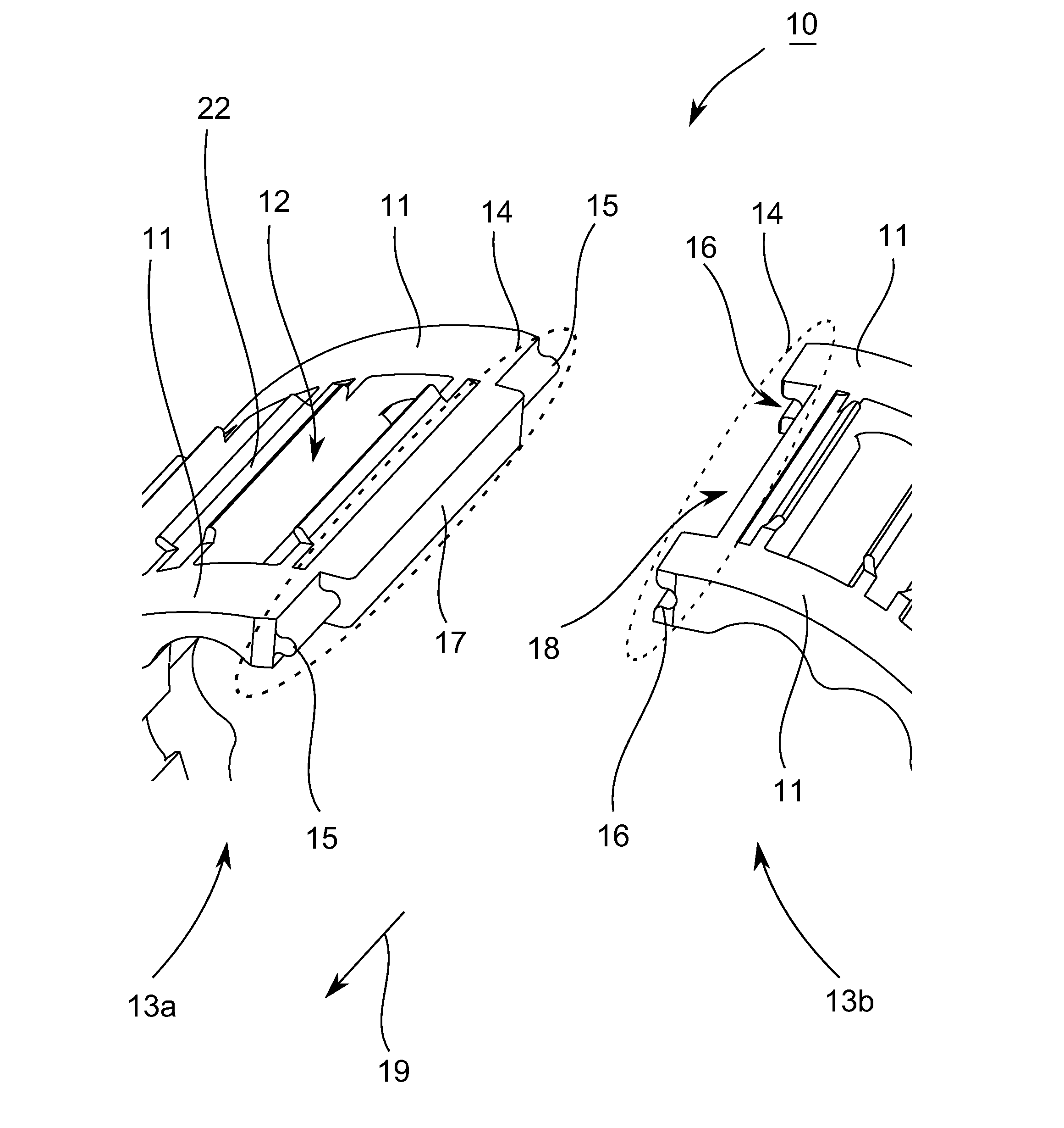
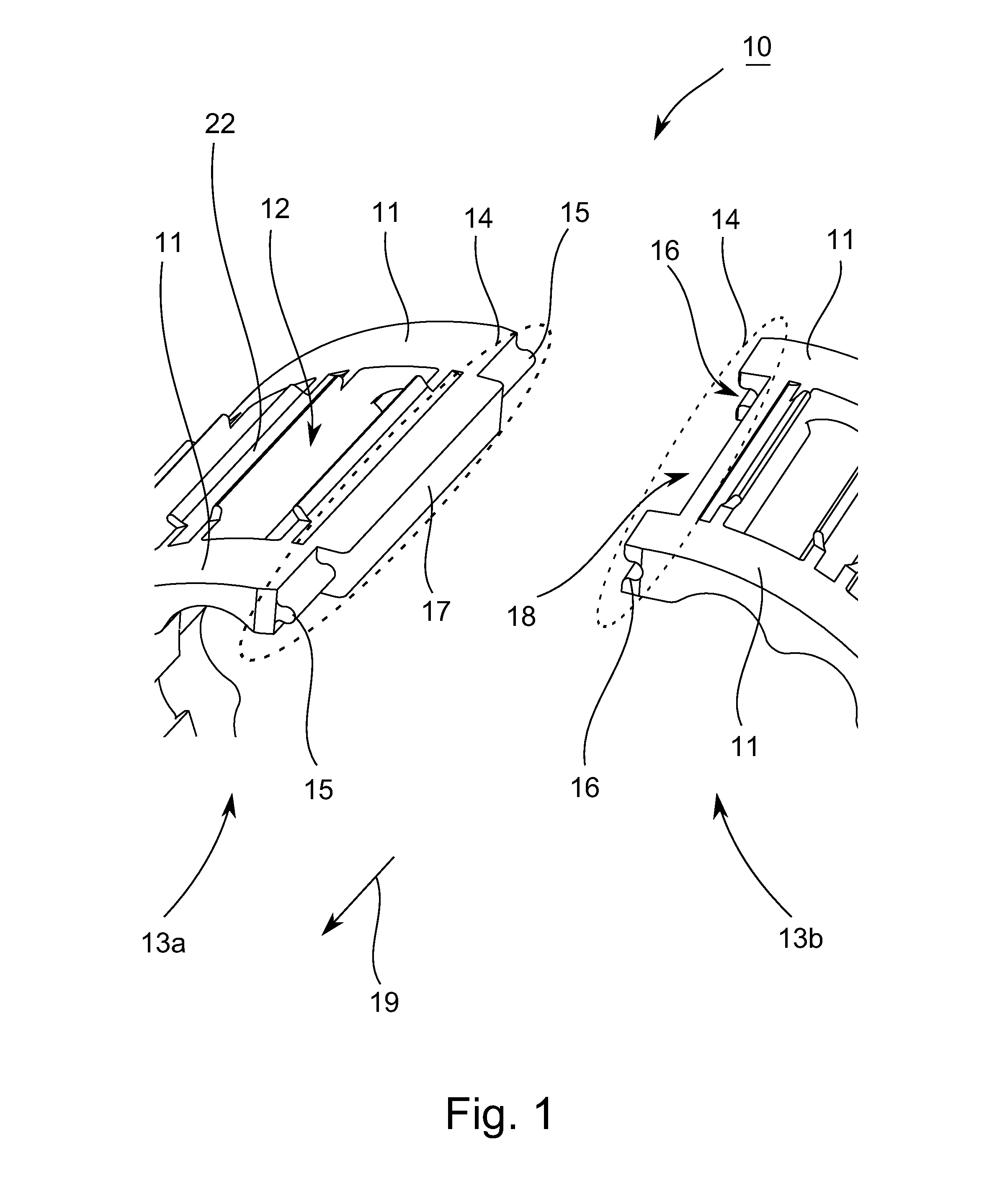
[0028]FIG. 1 shows a portion of a three-dimensional representation of a stepped split bearing cage 10 according to an exemplary embodiment of the present teachings.

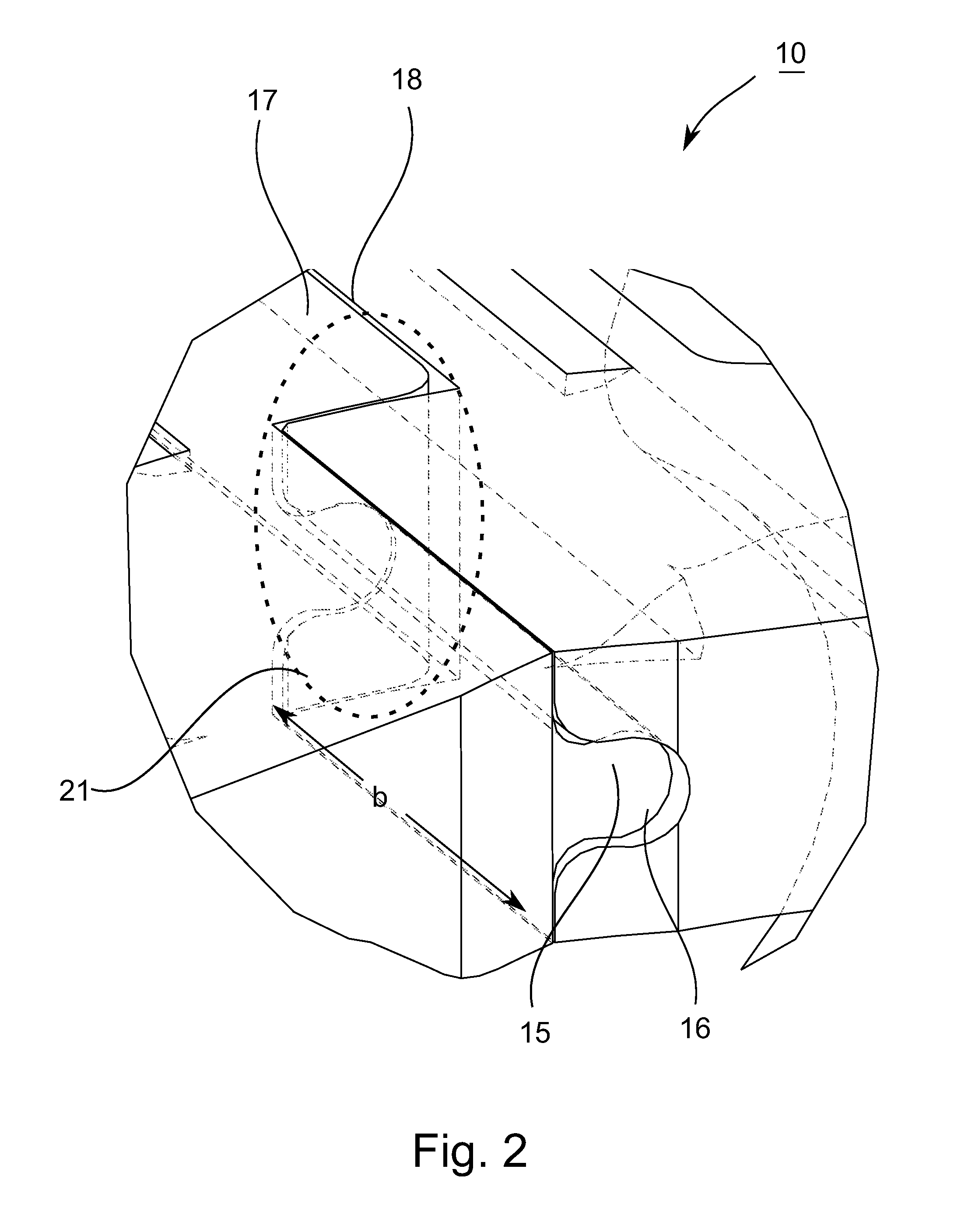
[0029]The bearing cage 10 has two axially spaced side rings 11, each extending in the circumferential direction of the bearing cage 10. Pockets 12 for accommodating or guiding rolling elements (not shown for purposes of clarity) can be disposed between the side rings 11. The rolling elements may be, without limitation, e.g., balls, cylindrical rollers, tapered rollers, spherical rollers, etc. The split bearing cage 10 is split in the circumferential direction along at least one cutting line (line of separation), thereby forming a split or gap between first and second bearing cage sections 13a, 13b. It should be understood that the first and second bearing cage sections 13a, 13b may be integrally connected together without a seam therebetween on ends opposite of the split or gap. Also, as referred to hereinbelow, the “tang...


PUM

PropertyMeasurementUnit
Lengthaaaaaaaaaa

Abstract

A rolling-element bearing cage includes two axially spaced-apart side rings extending in a circumferential direction. Each side ring is split in the circumferential direction along at least one cutting line, thereby defining bordering surfaces on first and second bearing cage sections. A plurality of connecting bridges connects the side rings in an axial direction. First and second pairs of mutually-opposing first projections and corresponding first openings are disposed on the side rings along the bordering surfaces of the first and second bearing cage sections and fix the bordering surfaces to each other in at least first and second directions that are perpendicular to each other. A pair of a second projection and a corresponding second opening is disposed axially between the first and second pairs of first projections and first openings and fixes the bordering surfaces to each other in a third direction perpendicular to the first and second directions.

Description

TECHNICAL FIELD[0001]The present invention relates to a split bearing cage, e.g., for rolling-element bearings, and a method for manufacturing such a bearing cage.BACKGROUND ART[0002]Bearing cages for rolling-element bearings are generally comprised of two axially-spaced-apart side rings and a plurality of bridges that connect the side rings and are disposed one behind the other in a circumferential direction of the bearing cage. Each pair of adjacent bridges forms a pocket for guiding a rolling element. The bearing cage thus holds the rolling elements spaced apart relative to each other, thereby preventing direct contact between neighboring rolling elements and thus reducing friction and heat generation in the bearing. The bearing cage also ensures a uniform distribution of the rolling elements around the entire circumference of the cage or rolling-element bearing and thus enables a uniform load distribution as well as a quiet and smooth running of the bearing.[0003]Bearing cages a...

Claims


Application Information

Patent Timeline
IPC IPC(8): F16C33/46B21D53/12
CPCF16C33/4694F16C33/4635F16C2226/74F16C2361/61F16C2361/53F16C19/24Y10T29/49691B21D53/12
Inventor STEBLAU, DIETER
Owner AB SKF
Learn More