
Ferrule and optical-fiber-attached ferrule

Active Publication Date: 2013-11-21
THE FUJIKURA CABLE WORKS LTD +1
View PDF3 Cites 26 Cited by
  • Summary
  • Abstract
  • Description
  • Claims
  • Application Information

AI Technical Summary

Benefits of technology

The invention can improve the accuracy of positioning in a joint by using a locating pin that is inclined relative to the ferrule main body, at a low cost. This may help to improve the efficiency and accuracy of assembly processes that require precise positioning.

Problems solved by technology

The degree of forming precision of the locating pin affects the positioning accuracy relative to the optical device of the ferrule and results in an increase in loss.
However, until now, there is not a preferred technique of improving the inclination of the locating pin with respect to the direction perpendicular to the joint surface of the ferrule main body as a practical matter.

Method used


Image

  • Ferrule and optical-fiber-attached ferrule
  • Ferrule and optical-fiber-attached ferrule
  • Ferrule and optical-fiber-attached ferrule

Examples


Embodiment Construction

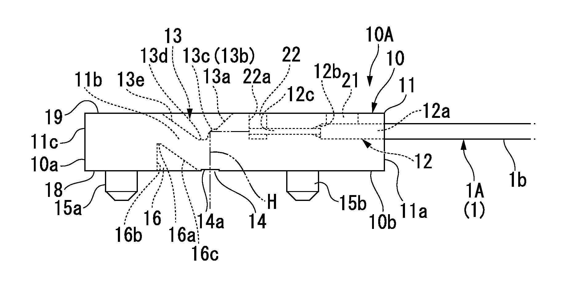
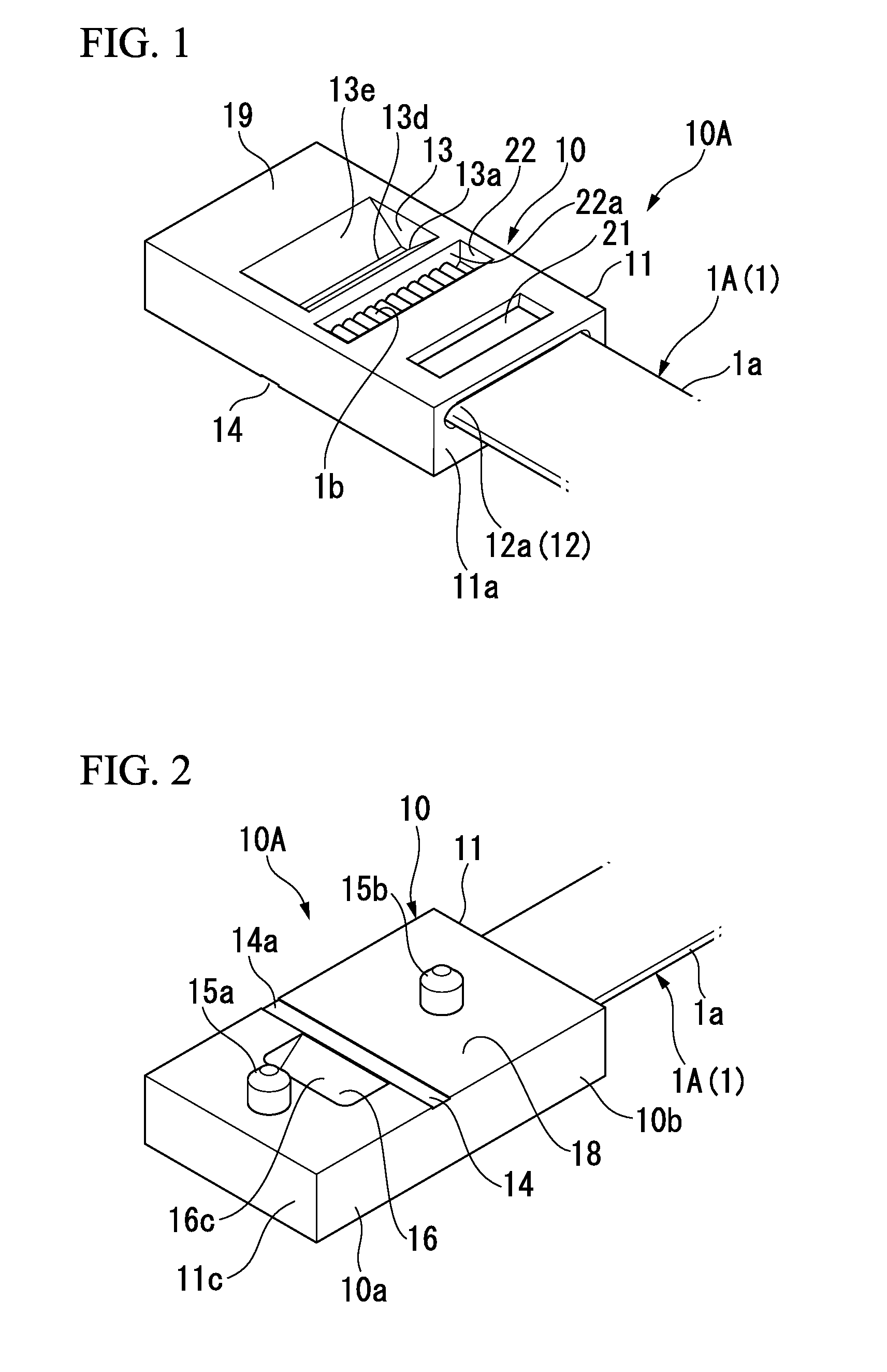
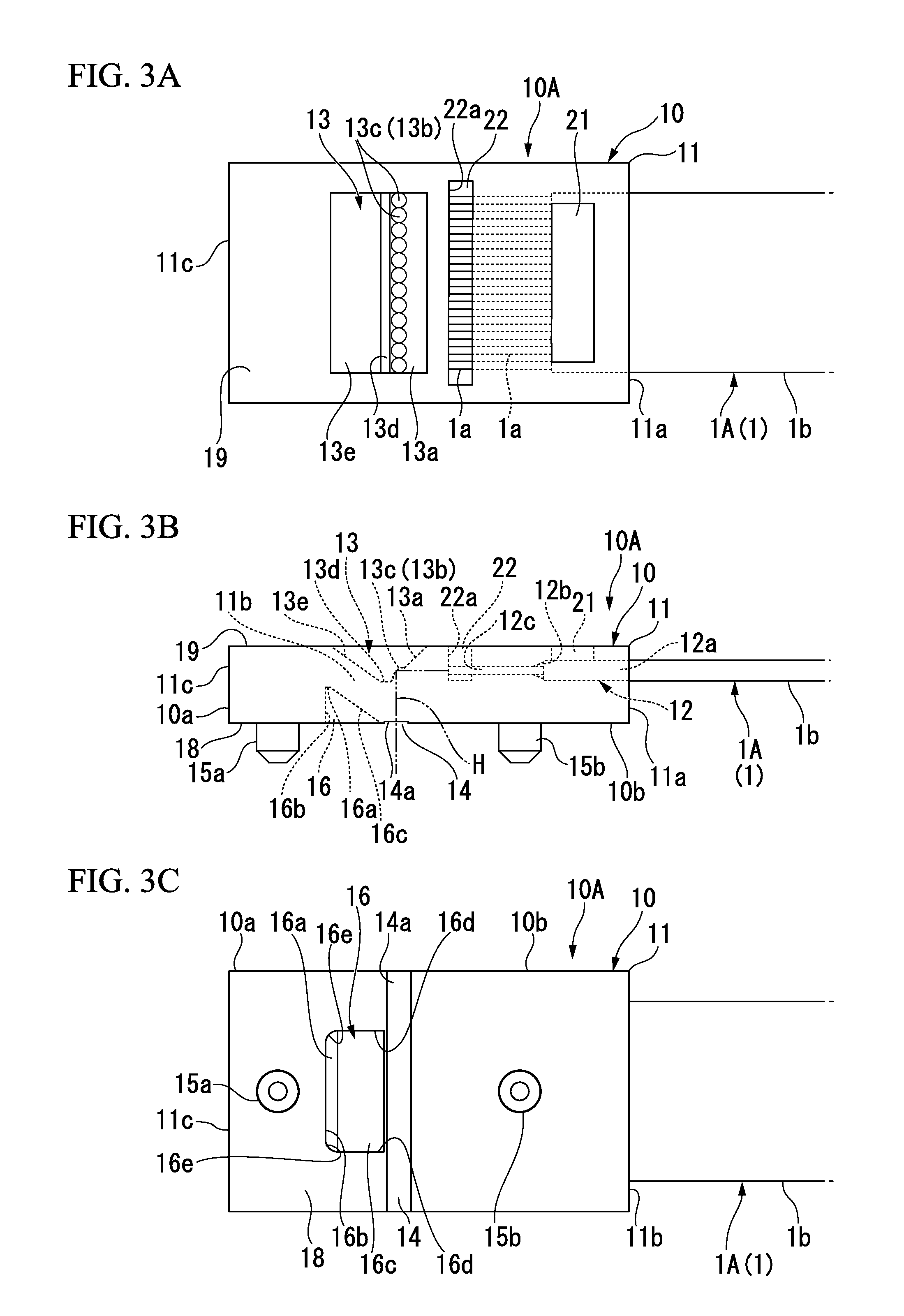
[0044]Hereinafter, a ferrule and an optical-fiber-attached ferrule of an embodiment of the invention will be described with reference to drawings.

[0045]As shown in FIGS. 1 to 4, a ferrule 10 is an integral molding article made of a transparent plastic possessing the refractive index greater than that of air such as acrylate resin or the like.

[0046]The ferrule 10 substantially has a structure in which a fiber insertion hole 12 into which the front-end portion of the optical fiber 1 is securely inserted, an optical-path changing recess 13, and a shaping-adjustment recess 16 (resin contraction adjustment recess) are formed on a plate-shaped ferrule main body 11.

[0047]In addition, the ferrule 10 has a pair of locating pins 15a and 15b protruding from a joint surface 18 that is one surface the ferrule main body 11.

[0048]As shown in FIG. 4, the joint surface 18 (connection surface) of the ferrule 10 is, for example, attached and connected to a ferrule-receiving surface 33a of a ferrule-re...


PUM


Abstract

A ferrule of the invention includes: a ferrule main body having a front edge and a rear edge; a fiber insertion hole into which an optical fiber is to be inserted; a recess provided at a top surface of the ferrule main body, having a reflection surface converting an optical path of a front end of the optical fiber into an optical path of a light emission-launch end provided at a lower surface side of the ferrule main body; a light emission-launch portion provided on the optical path of the light emission-launch end at a lower surface of the ferrule main body; a locating pin provided closer to the front edge than the light emission-launch portion at the lower surface of the ferrule main body; and a recessed portion provided between the locating pin at the lower surface of the ferrule main body and the light emission-launch portion.

Description

CROSS REFERENCE TO RELATED APPLICATIONS[0001]This application claims priority from Japanese Patent Application No. 2012-084382 filed on Apr. 2, 2012, the content of which is incorporated herein by reference in its entirety.BACKGROUND OF THE INVENTION[0002]1. Field of the Invention[0003]The present invention relates to a ferrule and an optical-fiber-attached ferrule in which a locating pin protruding from one surface thereof and an optical-path changing recess are formed at a plate-shaped transparent ferrule main body made of plastic which is to be attached to a front end of an optical fiber.[0004]2. Background Art[0005]As a ferrule to be attached to a front end of an optical fiber, a structure is known in which a pair of locating pins protruding from one surface thereof and an optical-path changing recess are formed at a plate-shaped transparent ferrule main body made of plastic (for example, Japanese Unexamined Patent Application, First Publication No. 2007-121973).[0006]The ferrul...

Claims


Application Information

Patent Timeline
IPC IPC(8): G02B6/38
CPCG02B6/381G02B6/3829G02B6/3885G02B6/4292G02B6/4214
Inventor NISHIMURA, AKITONUMATA, SHOTA
Owner THE FUJIKURA CABLE WORKS LTD
Learn More