
Systems and methods for interference mitigation in heterogeneous networks

a heterogeneous network and interference mitigation technology, applied in the field of communication networks, can solve the problems of cell edge performance, low performance compared to homogeneous network cell edge performance, interference between femto stations and macro stations

Inactive Publication Date: 2013-11-21
TAHOE RES LTD
View PDF4 Cites 48 Cited by
  • Summary
  • Abstract
  • Description
  • Claims
  • Application Information

AI Technical Summary

Benefits of technology

The patent text describes a system and method for reducing interference in heterogeneous networks, which includes a combination of low power, small footprint stations to increase system capacity and coverage in wireless communication networks. The technical effect of the patent is to improve the performance and reliability of heterogeneous networks by mitigating interference between different stations and optimizing resource allocation. The patent also describes various types of heterogeneous networks and their components, as well as methods for configuring and optimizing them. Overall, the patent provides a solution for enhancing network performance and improving user experience in wireless communication networks.

Problems solved by technology

Despite the significant indoor gains expected from deploying femto stations, there are numerous challenging technical problems, such as the interference between femto stations and macro stations.
The ICIC technique increases cell edge performance in heterogeneous networks, but the performance is still low compared to homogeneous network cell edge performance.
Macro users are satisfied because the interference is much less, but femto UEs suffer a decrease in power.
Further, if a femto user happens to stand in a position where the macro UE is located, there may be a problem in coverage for the femto UE.
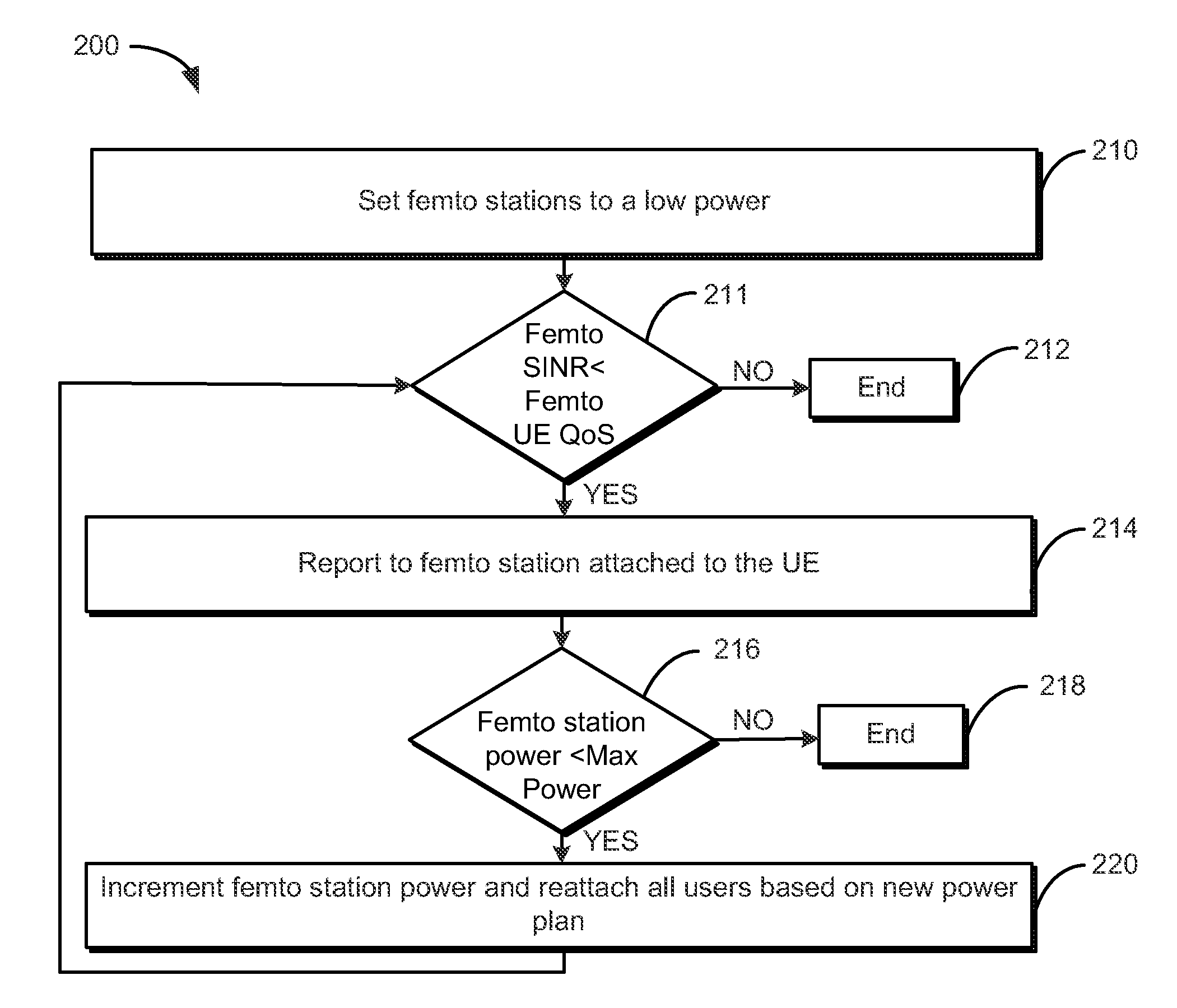
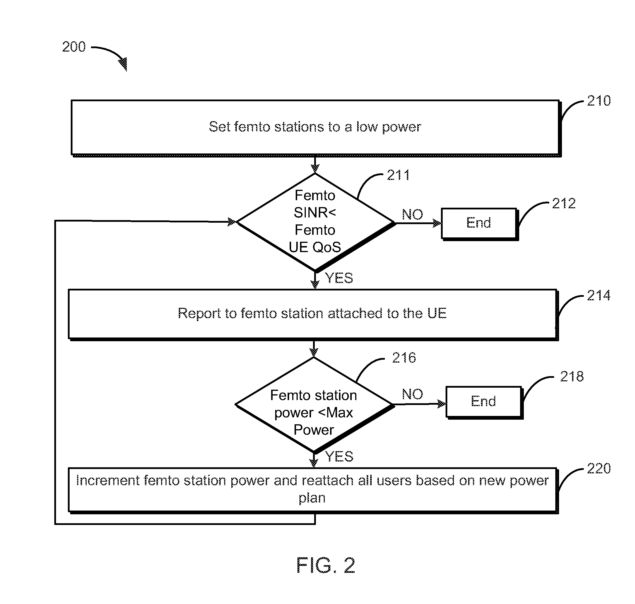
Also, if femto stations reach maximum power, no more increase can be done.
If, however, the femto station power is greater than the minimum power, the method 300 decrements 322 the femto station's power and reattaches all users based on the new power plan.
Generally, however, sharing resources or reducing the femto station's power for all deployed femto stations results in lower femto throughput, which in turn limits the expected gains from the deployed femto stations.
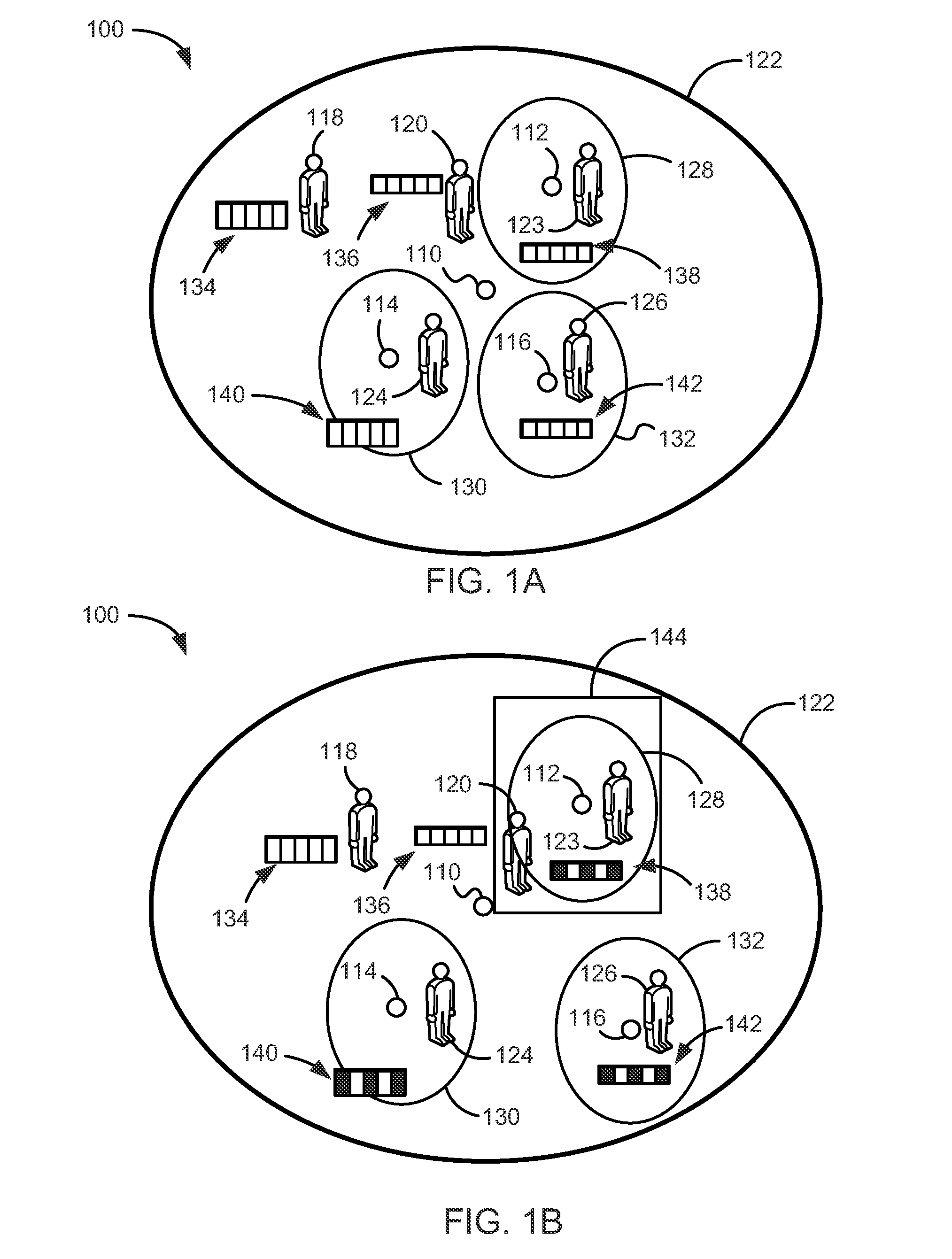
As discussed in detail below, deploying femto cells increases the SINR of femto UEs and may cause limited degradation to the performance of the outdoor macro UEs.
However, the applicants have recognized that the macro indoor UEs are “victim” UEs of prior attempts at interference mitigation.
In other words, prior attempts at interference mitigation have dramatically reduced the SINR performance of the macro indoor UEs.
Analysis of the model described above reveals problems with femto heterogeneous networks.
However, the macro indoor UEs have dramatic degradation as the macro indoor UEs receive a large amount of interference from the femto stations.
Although conventional ICIC gives a great advantage to macro users, its scheduling is not efficient.
A problem with S-ICIC and conventional ICIC is that they cause high degradation in the network capacity when compared with a femto baseline.
The capacity degradation is caused by the large percentage of shut off femto station resources.
This is due to the observation that only 15% of femto stations apply the ICIC algorithm, which is not sufficient to improve all the macro indoor UEs.
However, deploying femto stations decreases the SINR of the macro indoor UEs.
AP-A-MUZF provides high cell edge performance and capacity, but may have high complexity in certain embodiments, due to the MUZF complexity.
A problem that may occur with FF-AP is that it does not take into consideration the effect of the power increase over the macro UEs SINR, which may lead to reducing the performance of the macro UEs.
But, MF-AP may lead the femto UEs to suffer greatly due to a high decrease in the femto station power.
Femto users are not served as well as they are in normal AP-FF because their QoS is no longer guaranteed to be satisfied.
A major challenge facing heterogeneous networks is the interference between different power nodes and its dramatic effect on the macro UEs.
But, AP-MC-A-ICIC may have a high complexity.

Method used


Image

  • Systems and methods for interference mitigation in heterogeneous networks
  • Systems and methods for interference mitigation in heterogeneous networks
  • Systems and methods for interference mitigation in heterogeneous networks

Examples


example performance

VII. EXAMPLE PERFORMANCE ANALYSIS

[0097]Table 5 shows example results of running different simulations for 20 runs. In this example, the Femto cells and UE deployment differ from one run to the other to cover different states of randomization. Each run simulates 100 frames.

TABLE 5Simulation ResultsCELLCAPACITYCELL-EDGE% OF FSsSCENARIO(b / s / Hz)(b / s / Hz)AFFECTEDFF-AP12.5680.037N / AMF-AP10.4330.041N / AFF-AP-MC12.3710.041N / AMF-AP-FC10.6010.037N / AMF-AP-ICIC6.5460.043100MF-AP-A-ICIC9.5830.02724.4FF-AP-MC-A-ICIC11.190.04723

[0098]In Table 5, the AP embodiments may be evaluated against various scenarios shown in Table 4: macro-only, femto baseline, ICIC, and AP basic algorithms. These algorithms are evaluated in terms of total area SE and the cell-edge SE. In this example, the total area SE is the SE achieved over the sector area, which includes one macro station and six femto stations. In the macro-only scenario, none of the femto stations transmits data, while the femto baseline case represents...


PUM


Abstract

Disclosed systems and methods mitigate interference in heterogeneous networks. Embodiments include adaptive or selective inter-cell interference coordination, adaptive multi-user zero forcing, adaptive power, and / or combinations of the foregoing. Techniques may be used to favor one group of users (e.g., femto users or macro users) over another. Certain embodiments focus quality of service (QoS) improvements on a first group of users, while using constraint processes to provide a threshold QoS for a second group of users.

Description

RELATED APPLICATION[0001]This application claims the benefit under 35 U.S.C. §119(e) of U.S. Provisional Application No. 61 / 648,426, filed May 17, 2012, which is hereby incorporated by reference herein in its entirety.TECHNICAL FIELD[0002]This disclosure relates to communication networks. Specifically, this disclosure relates to systems and methods for mitigating interference in heterogeneous networks.BACKGROUND[0003]A need for higher data rates in wireless communication systems has arisen from a rapid advancement of wireless handheld device technologies. To cover the need for increased capacity, heterogeneous networks were introduced. Heterogeneous networks include a hierarchical deployment of low power, small footprint stations to increase system capacity and coverage within a larger coverage area. For example, femto cells, pico cells, relays, and / or distributed antennas may be used within a macro cell coverage area. However, the femto cells, pico cells, relays, and / or distributed...

Claims


Application Information

Patent Timeline
Patent Type & Authority Applications(United States)
IPC IPC(8): H04W72/08H04W72/54
CPCH04W72/082Y02B60/50H04W72/00H04W84/045H04B17/27H04W52/241H04W52/265H04W52/143H04W52/244H04L5/0073H04B7/024Y02D30/70H04W72/541
Inventor IBRAHIM, AHMED S.MAKLED, ESRAA A.ELGEBALY, HANI H.DARWISH, AHMED M.
Owner TAHOE RES LTD
Learn More