System And Method For Design Of Subsurface Drainage Systems Incorporating Control Weirs, Surface To Subsurface Inlets, And Irrigation Inlets

Inactive Publication Date: 2013-11-21
MEINERS CHAD R +2
View PDF7 Cites 26 Cited by
  • Summary
  • Abstract
  • Description
  • Claims
  • Application Information

AI Technical Summary

Benefits of technology

[0025]In another embodiment, the present invention is a method for generating a subsurface drainage and irrigation system design that maintains a set slope and consistent depth for tile laterals throughout a specified area. In the method, a management computer and a contour map of said specified area are used to place a tile main in said design, wherein said tile main extends from an outlet to a location of highest elevation in said specified area, wherein a path taken by said tile main follows an outside border of the specified area. The management computer determines a required slope of the tile main so as to minimize the number of changes in slope in said tile main while maintaining said tile main within a bounded depth range from the ground level. A desired bounded distance from tile lateral to tile lateral, grade, and bounded depth range from ground level is inputted into the management computer using an input device. The management computer places a first tile lateral connecting to said tile main, wherein said first tile lateral is placed at a starting location, direction, and footage so as to maintain inputted entered desired bounded distance from tile lateral to tile lateral, slope, and bounded depth range from ground level and wherein a new direction and a footage of the new direction of said first tile lateral are determined by said management computer until a final defined footage of said first tile lateral is reached. The management computer places in the design a second tile lateral connecting to said tile main, wherein said second tile lateral is placed at a starting location, direction, and footage, wher

Problems solved by technology

This repeated conversion degrades the

Method used


Image

  • System And Method For Design Of Subsurface Drainage Systems Incorporating Control Weirs, Surface To Subsurface Inlets, And Irrigation Inlets
  • System And Method For Design Of Subsurface Drainage Systems Incorporating Control Weirs, Surface To Subsurface Inlets, And Irrigation Inlets
  • System And Method For Design Of Subsurface Drainage Systems Incorporating Control Weirs, Surface To Subsurface Inlets, And Irrigation Inlets

Examples


Embodiment Construction

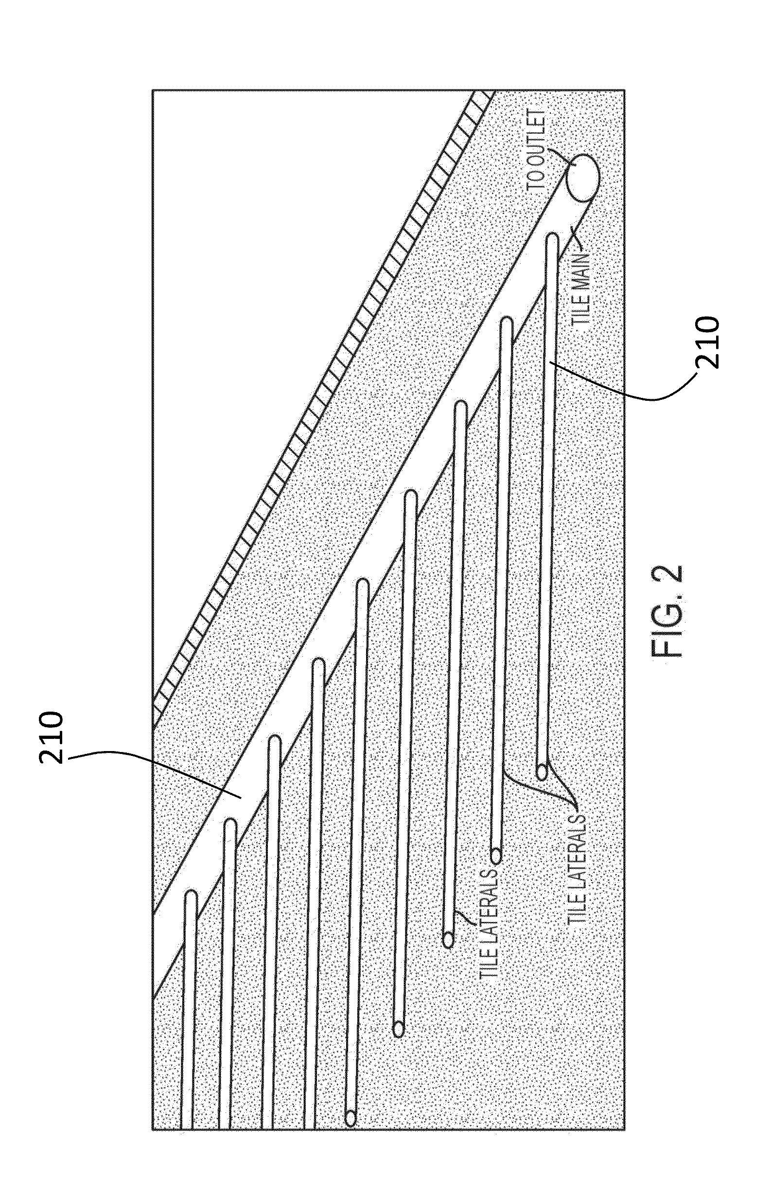
[0035]Preferred embodiments of the present invention will be described with reference to FIGS. 1-8. A subsurface system may be comprised of a variety of different components. As shown in FIG. 2, a simple system may have a tile main 210 and a plurality of tile laterals 220. A more complicated subsurface system, as shown in FIG. 3, may include a tile main 310, a plurality of tile laterals 320 and a plurality of control weirs 330 each having a control gate 332 within it. In another variation as shown in FIG. 4, a subsurface system may have a tile main 410, a plurality of tile laterals 420, and one or more post risers 430. The tile main 410 may have an enlarged section or portion 412 to accommodate the riser 430. Further, as shown in FIG. 5, a tile main 510 may have a plurality of tile laterals 520, one or more of which may be increased in size 522 due to their length. A yet more complicated subsurface system is shown in FIG. 6. A tile main 610 has a plurality of tile laterals 620 conne...


PUM


Abstract

A method for the creation of subsurface water management systems that place subsurface drainage lines at a consistent grade and within defined elevation bounds throughout a field with topographical undulation and inconsistent slopes, incorporate control weirs for dividing the subsurface into elevation and acreage zones, place and size surface to subsurface, size and determine inside surface of drainage mains and laterals according to the desired coefficient of the subsurface system, and determine the amount of water required at irrigation inlets in order to deliver a determined amount of water into the subsurface system for purposes of irrigation.

Description

CROSS-REFERENCE TO RELATED APPLICATIONS[0001]The present application claims the benefit of the filing date of U.S. Provisional Patent Application Ser. No. 61 / 647,237 filed by the present inventors on May 15, 2012.[0002]The aforementioned provisional patent application is hereby incorporated by reference in its entirety.STATEMENT REGARDING FEDERALLY SPONSORED RESEARCH OR DEVELOPMENT[0003]None.BACKGROUND OF THE INVENTION[0004]1. Field of the Invention[0005]The present invention relates broadly to the field of agriculture, and more specifically to the use of topographic data in the field of agriculture[0006]2. Brief Description of the Related Art[0007]In the field of agriculture, irrigation systems water crop fields, and tile systems manage water drainage in crop fields. Often, irrigation and tile systems are “sub surface,” or installed underground. Networks of pipe and / or tubing are installed underground for both systems, including main collector lines and a number of outlets. Outlets...

Claims


Application Information

Patent Timeline
IPC IPC(8): G06F17/50
CPCG06F17/5004G06F30/13G06F2113/14
Inventor MEINERS, CHAD R.MEINERS, JEREMY R.MEINERS, ROBERT E.
Owner MEINERS CHAD R
Why Eureka
Try Eureka