Combined cycle power plant with co2 capture plant

a technology of co2 capture and power plant, which is applied in the direction of machines/engines, lighting and heating apparatus, separation processes, etc., can solve the problems of reducing the overall and achieve the effect of increasing the efficiency of the power plan

Inactive Publication Date: 2013-11-28
ALSTOM TECH LTD
View PDF25 Cites 27 Cited by
  • Summary
  • Abstract
  • Description
  • Claims
  • Application Information

AI Technical Summary

Benefits of technology

[0009]It is an object of the present invention to provide a combined cycle power plant operating with a CO2 capture plant having increased power plant efficiency over known power plants of this type.

Problems solved by technology

A CO2 capture plant of this type requires a given amount of energy, which reduces the overall efficiency of the power plant.

Method used


Image

  • Combined cycle power plant with co2 capture plant
  • Combined cycle power plant with co2 capture plant
  • Combined cycle power plant with co2 capture plant

Examples


Embodiment Construction

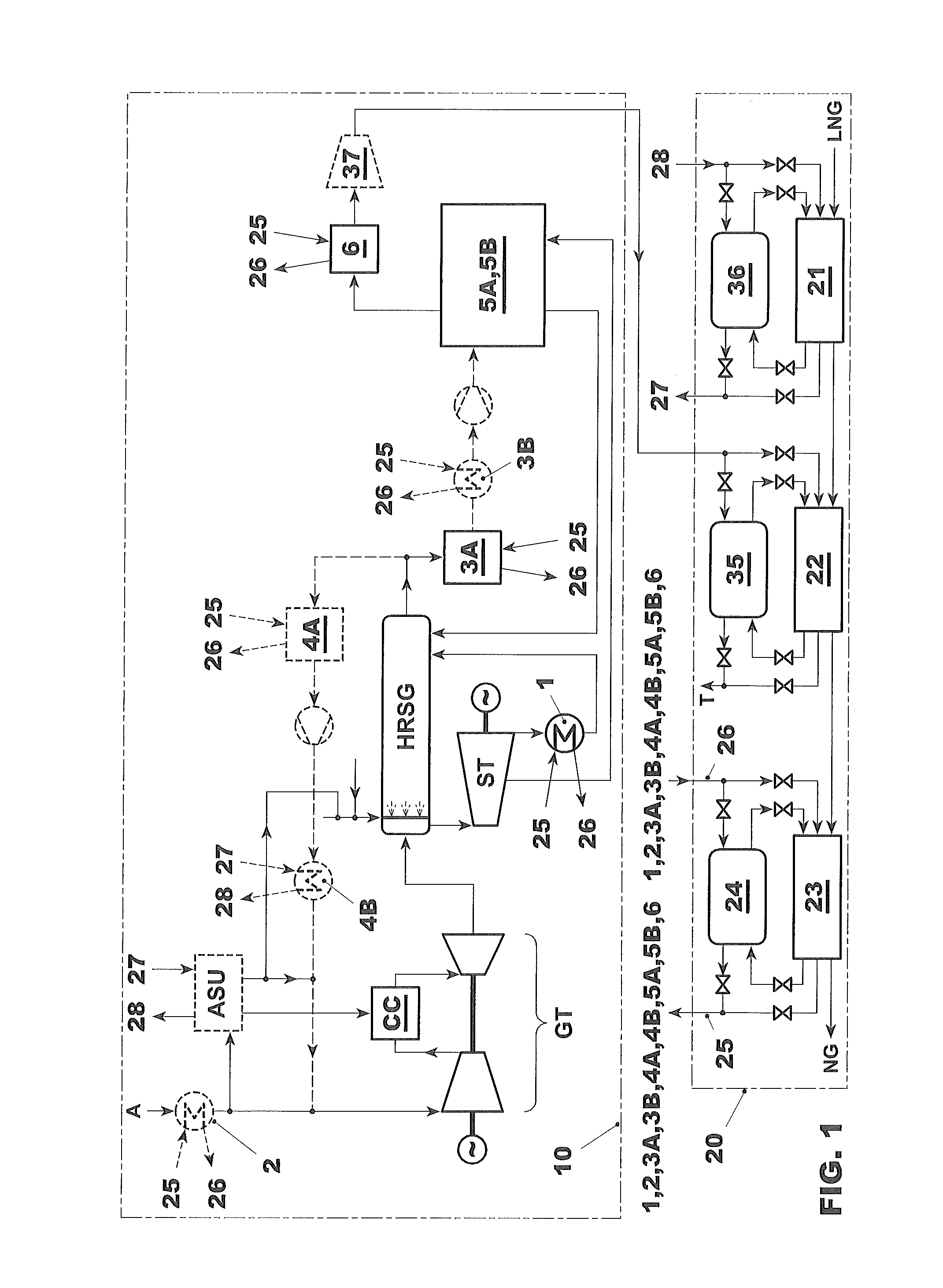
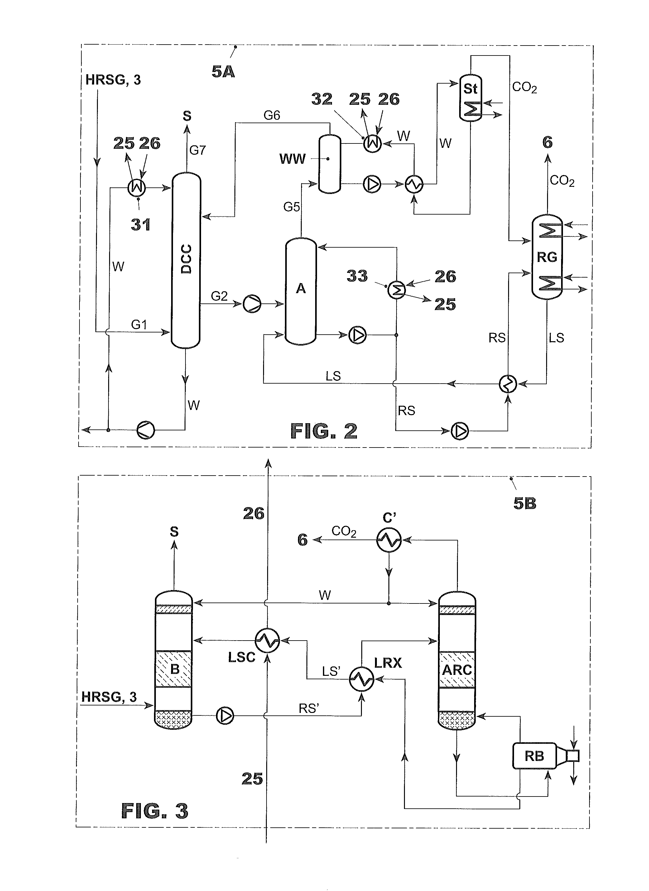
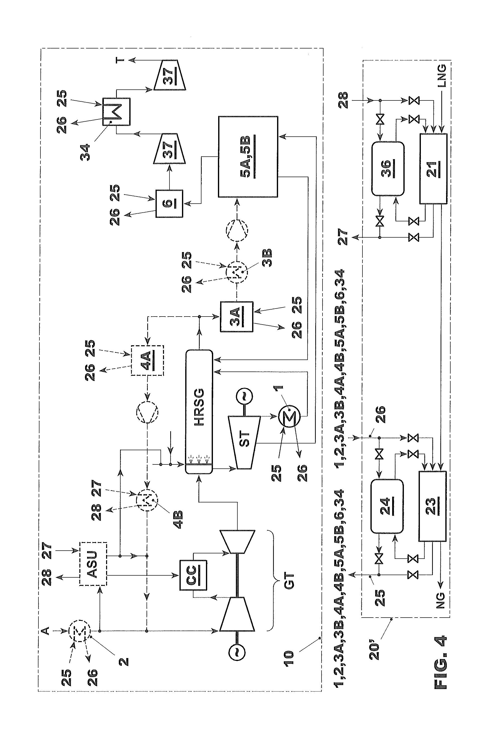
[0043]FIG. 1 depicts a combined cycle power plant 10 for the generation of electricity with a gas turbine GT provided with ambient air A, a heat recovery steam generator HRSG, which generated steam using the hot exhaust gases from the gas turbine, and steam turbine ST driven by steam generated in the HRSG. A condenser 1 condenses the expanded steam and the condensate is directed as feedwater to the HRSG thereby completing the water / steam cycle of the steam turbine. The power plant furthermore comprises a CO2 capture system 5A, 5B, which can be either a system operating on the basis of a chilled ammonia process (as shown in as 5A in FIG. 2) or a system based on a amine process (as shown as 5B in FIG. 3).

[0044]The gas turbine of power plant 10 is operated with natural gas supplied by the liquefied natural gas LNG regasification plant 20. The power plant 10 is operatively connected with a LNG processing system 20 having one more stages, which vaporizes cryogenic liquefied natural gas L...


PUM

PropertyMeasurementUnit
chilling temperaturesaaaaaaaaaa
temperaturesaaaaaaaaaa

Abstract

A combined cycle power plant includes a CO2 capture system operatively integrated with a liquefied natural gas LNG regasification system, where cold energy from the regasification process is used for cooling processes within the CO2 capture system or processes associated with it. These cooling systems include systems for cooling lean or rich absorption solutions for the CO2 capture or the cooling of flue gas. The LNG regasification system is arranged in one or more heat exchange stages having and one or more cold storage units. The power plant with CO2 capture can be operated at improved overall efficiencies.

Description

CROSS-REFERENCE TO RELATED APPLICATIONS[0001]This application claims priority to PCT / EP2012 / 051267 filed Jan. 26, 2012, which in turn claims priority to European Application 11152823.8 filed on Feb. 1, 2011, both of which are hereby incorporated in their entirety.TECHNICAL FIELD [0002]The present invention pertains to a combined cycle power plant for the generation of electric power having a gas turbine, a steam turbine, and a heat recovery steam generator, and furthermore a plant for the capture and compression of carbon dioxide. The invention pertains in particular to an integration of a liquefied natural gas processing system with the power plant.BACKGROUND ART[0003]Combined cycle power plants for the generation of electricity are known to include a gas turbine, a steam turbine, and a heat recovery steam generator utilizing the hot flue gases emitted by the gas turbine to generate steam to drive the steam turbine. In order to reduce emissions that contribute to the greenhouse eff...

Claims


Application Information

Patent Timeline
Patent Type & Authority Applications(United States)
IPC IPC(8): F01K23/10C01B32/50
CPCF01K23/10B01D53/1425B01D53/1475B01D2252/102F01K13/00F01K23/064F01K23/068F22B1/1815F25J3/04018F25J3/04266F25J3/04533F25J3/04593F25J2210/62F25J2210/70F25J2230/02F25J2230/80F25J2240/82F25J2260/80F25J2270/904Y02E20/14Y02E20/16Y02E20/18Y02E20/32Y02C20/40
Inventor WIRSUM, MANFREDRUCHTI, CHRISTOPHLI, HONGTAODROUX, FRANCOISKOZAK, FREDERIC ZENONZAGORSKIY, ALEXANDER
Owner ALSTOM TECH LTD
Why Eureka
Try Eureka