
Method to detect loss of fluid or blockage in a hydraulic circuit using exponentially weighted moving average filter

a filter and exponential weight technology, applied in the direction of gearing details, machines/engines, instruments, etc., can solve the problems of transmission components not being adequately cooled and lubricated, low fluid levels, and damage to transmission components

Active Publication Date: 2013-11-28
GM GLOBAL TECH OPERATIONS LLC
View PDF15 Cites 8 Cited by
  • Summary
  • Abstract
  • Description
  • Claims
  • Application Information

AI Technical Summary

Benefits of technology

The patent is for a method to detect faults in a car's hydraulic system using an electric pump. The method involves measuring the actual pump torque and comparing it to a desired pump torque. A confidence factor is determined based on the actual pump torque and the desired pump torque. An average confidence factor is calculated based on the current confidence factor and previous confidence factors. The average confidence factor is then compared to a fault condition threshold. If the average confidence factor is at least the threshold, the hydraulic system is considered to be in a normal condition. If the average confidence factor is below the threshold, the hydraulic system is considered to be in a fault condition. This method allows for timely detection of hydraulic system faults and prevents damage to the system.

Problems solved by technology

Therefore, failure conditions including fluid leakage resulting in low fluid levels and hydraulic fluid blockage within the hydraulic circuit will not have any impact on the ability of the transmission to provide output torque for driving the vehicle.
However, failure conditions can result in transmission components not being adequately cooled and lubricated.
Damage to the transmission components can occur if such failure conditions are not addressed.
Such sensors and measuring devices can add to cost and limit packaging constraints within hydraulic control systems.

Method used


Image

  • Method to detect loss of fluid or blockage in a hydraulic circuit using exponentially weighted moving average filter
  • Method to detect loss of fluid or blockage in a hydraulic circuit using exponentially weighted moving average filter

Examples


Embodiment Construction

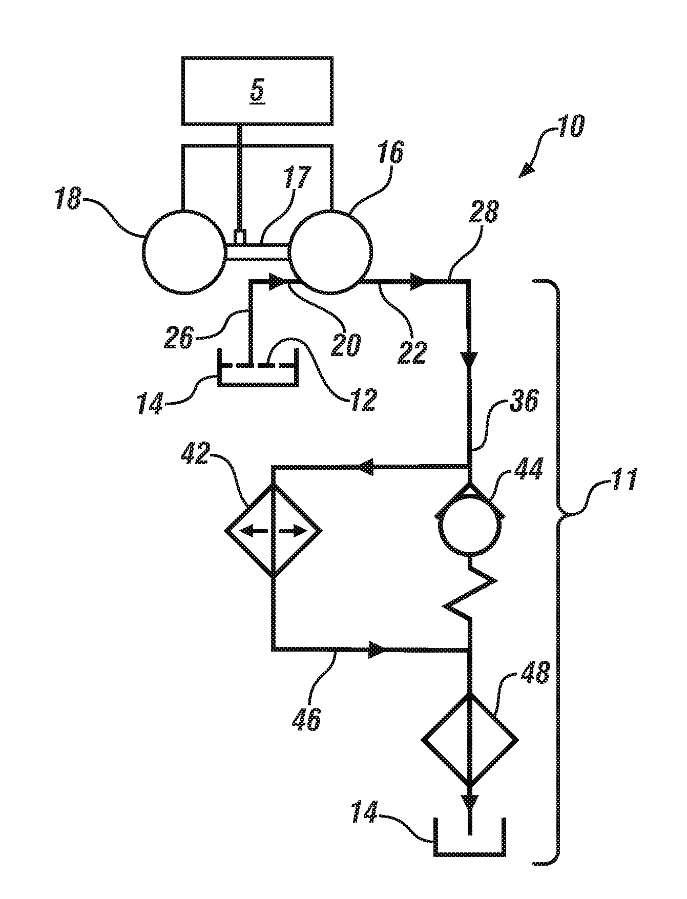
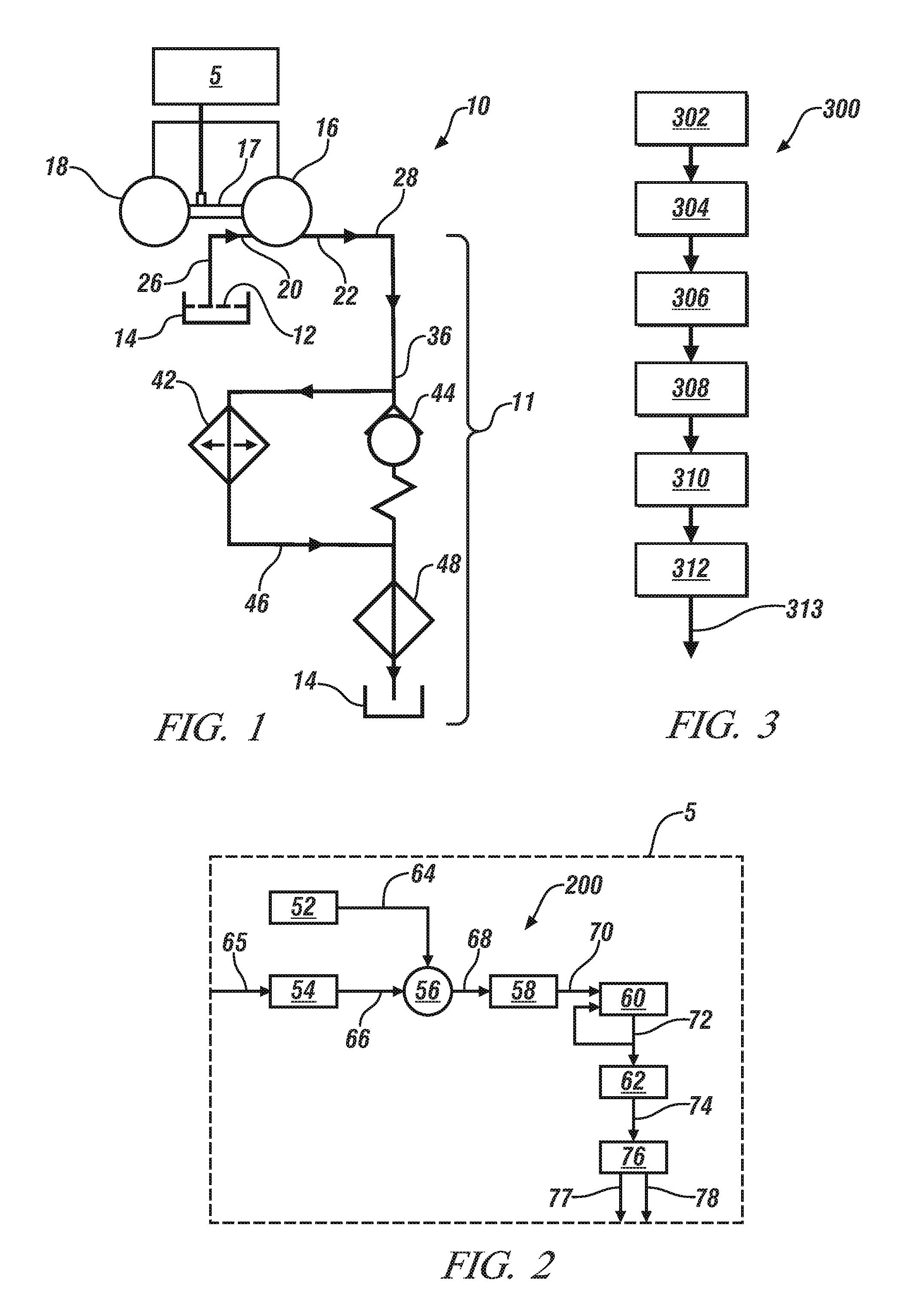
[0013]Referring now to the drawings, wherein the showings are for the purpose of illustrating certain exemplary embodiments only and not for the purpose of limiting the same, FIG. 1 schematically illustrates an exemplary hydraulic control system 10 for a transmission. In an exemplary embodiment, the transmission is a direct drive transmission for a battery electric vehicle. Therefore, the direct drive transmission does not include a gear selection system utilizing torque transfer devices that are hydraulically activated and deactivated. The hydraulic control system 10 is operable to lubricate and provide temperature management of the transmission by communicating a hydraulic fluid 12 from a sump 14 to at least one of a plurality of subsystems of a hydraulic circuit 11. The plurality of subsystems of the hydraulic circuit 11 can include a cooler subsystem 42 and a lubrication and temperature management subsystem 48. However, the hydraulic circuit 11, in some embodiments, may only inc...


PUM


Abstract

Method for detecting a fault condition in a vehicular hydraulic circuit during a drive cycle using an electric pump includes monitoring an actual pump torque and monitoring a desired pump torque. A current confidence factor is determined based on the actual pump torque and the desired pump torque. An average confidence factor is iteratively calculated based on the current confidence factor and previously determined confidence factors. The average confidence factor is compared to a fault condition threshold. An absence of the fault condition in the hydraulic circuit is detected when the average confidence factor is at least the fault condition threshold, and a presence of the fault condition in the hydraulic circuit is detected when the average confidence factor is less than the fault condition threshold.

Description

TECHNICAL FIELD[0001]This disclosure is related to hydraulic control systems for direct drive transmissions.BACKGROUND[0002]The statements in this section merely provide background information related to the present disclosure. Accordingly, such statements are not intended to constitute an admission of prior art.[0003]Hydraulic systems for a transmission in a vehicle can lubricate and cool the transmission by communicating a hydraulic fluid from a sump to at least one of a plurality of subsystems of a hydraulic circuit. In battery electric vehicles, the transmission can include a direct drive transmission. Direct drive transmissions do not include gear selection systems utilizing torque transfer devices that are hydraulically activated and deactivated. Therefore, failure conditions including fluid leakage resulting in low fluid levels and hydraulic fluid blockage within the hydraulic circuit will not have any impact on the ability of the transmission to provide output torque for dri...

Claims


Application Information

Patent Timeline
IPC IPC(8): G06F11/30F16N29/00F16N7/38F16N29/04
CPCF16H57/0442F16H2061/1208F16H61/0031F16H61/12
Inventor NAQVI, ALI K.ZETTEL, ANDREW M.RAWLS, VINCENTKOKOTOVICH, NICHOLAS
Owner GM GLOBAL TECH OPERATIONS LLC
Learn More