Wound Core Scot Transformer
- Summary
- Abstract
- Description
- Claims
- Application Information
AI Technical Summary
Benefits of technology
Problems solved by technology
Method used
Image
Examples
embodiment 1
[0023]In the present embodiment, a configuration of a wound core Scott transformer will be described.
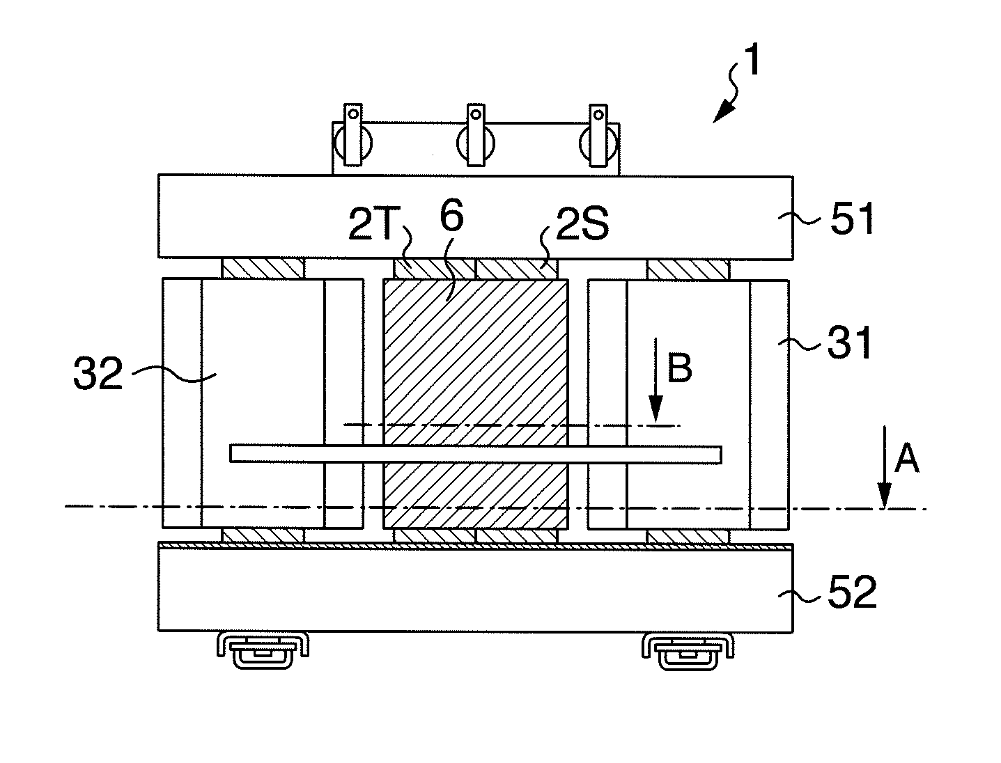
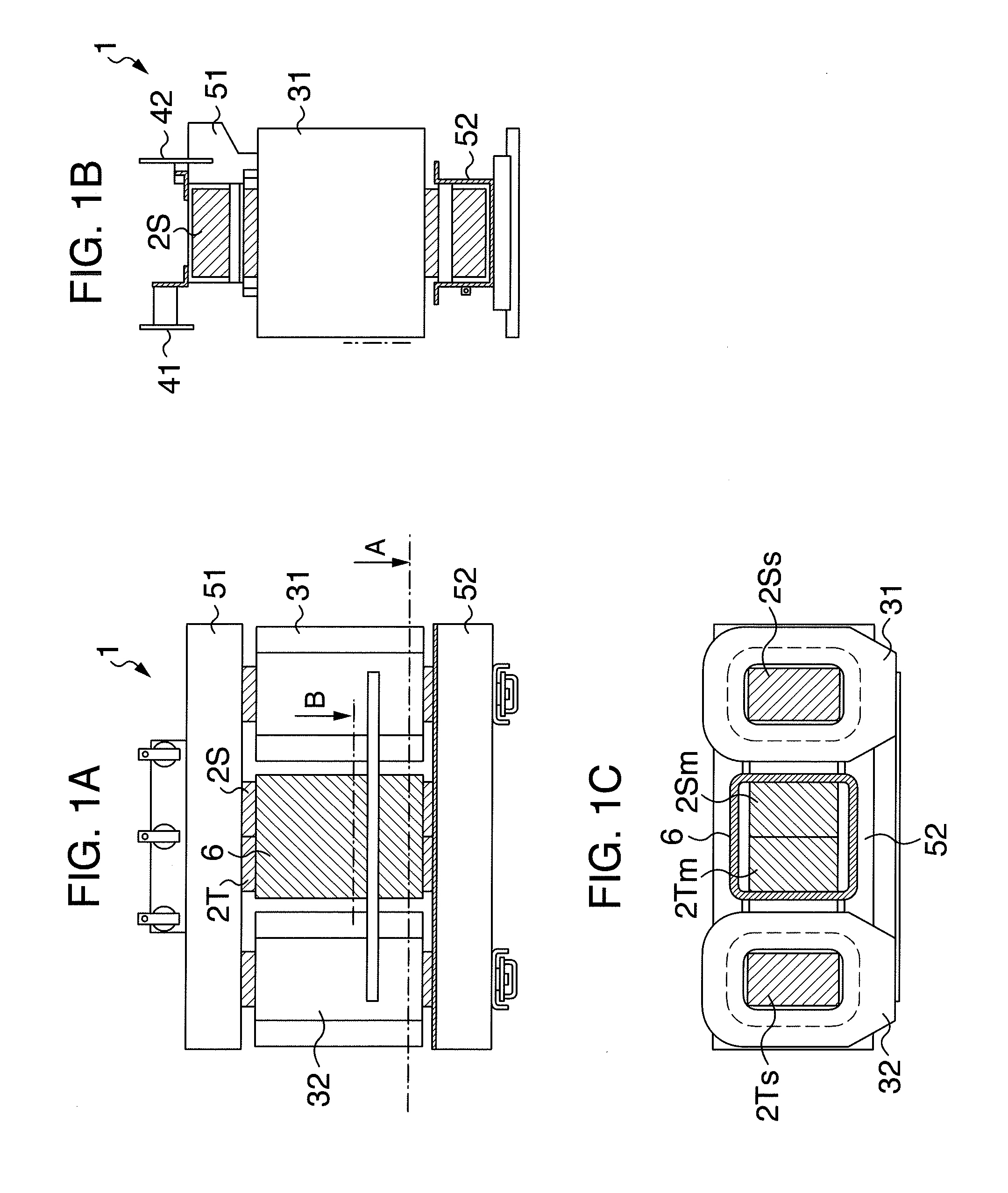
[0024]FIGS. 1A, 1B, and 1C are, respectively, a front view, a side view, and a plan view of the wound core Scott transformer of the present embodiment.
[0025]The wound core Scott transformer 1 for power receiving and distribution includes a main core 2S, a teaser core 2T, a main coil 31, a teaser coil 32, a first terminal 41, a second terminal 42, an upper metal fitting 51, and a lower metal fitting 52.
[0026]The main coil 31 is mounted to the main core 2S, and the teaser coil 32 is mounted to the teaser core 2T.
[0027]As shown in the plan view of FIG. 1C, a core leg of the main core 2S on which the main coil 31 is mounted is referred to as a main coil mounting core leg 2Ss, and a core leg of the main core 2S on which the main coil 31 is not mounted is referred to as a main coil non-mounting core leg 2Sm.
[0028]Further, a core leg of the teaser core 2T on which the teaser coil 32 is moun...
embodiment 2
[0037]In the present embodiment, a method of preventing deformation of a wounded core by a plate-like member will be described.
[0038]FIGS. 2A to 2C are configuration diagrams of a wounded core Scott transformer of the present embodiment. Within the wounded core Scott transformer configuration diagrams of FIGS. 2A to 2C, description of parts having functions identical to the previously described components with the same reference characters are omitted.
[0039]In the embodiment 1, an example is illustrated in which the shapes of the inside core legs on which no coil is mounted (the main coil non-mounting core leg 2Sm and the teaser coil non-mounting core leg 2Tm) are retained using the resin bobbin that is a cylindrical member.
[0040]In the embodiment of FIGS. 2A to 2C, the shapes of inside core legs on which no coil is mounted (the main coil non-mounting core leg 2Sm and the teaser coil non-mounting core leg 2Tm) are supported by a supporting member formed in a plate-like shape instead...
embodiment 3
[0045]In the present embodiment, one example of a manufacturing method of a resin bobbin will be described.
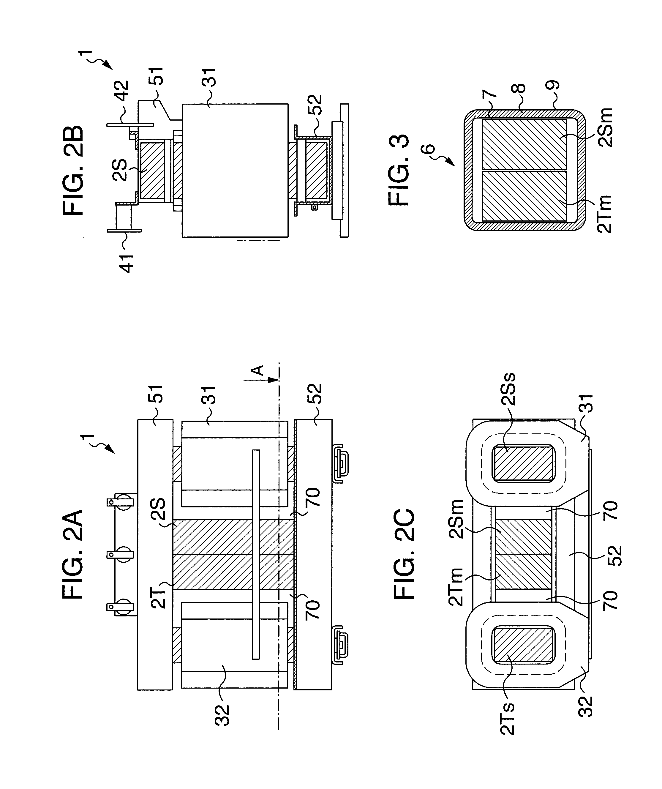
[0046]FIG. 3 shows a cross sectional view of section A in FIG. 1A, and is a configuration diagram of a resin bobbin of the present embodiment.
[0047]In the manufacturing method of the resin bobbin 6 molded from resin, a former is arranged along the inner circumference, and an inner circumferential insulating film 7 is wound around the former so that it is arranged at the most inner circumference of the bobbin. For example, a polyester material may be used as the inner circumferential insulating film. In order to obtain the thickness of the bobbin, a glass base material layer 8, for example, including a plurality of glass base material insulators is provided on the inner circumferential insulating film, and then an outer circumferential insulating film is wound thereon at the most outer circumference. For example, a polyester material may be used as the outer circumferential insu...
PUM
 Abstract
Description
Claims
Application Information
 - R&D
- Intellectual Property
- Life Sciences
- Materials
- Tech Scout
- Unparalleled Data Quality
- Higher Quality Content
- 60% Fewer Hallucinations
Browse by: Latest US Patents, China's latest patents, Technical Efficacy Thesaurus, Application Domain, Technology Topic, Popular Technical Reports.
© 2025 PatSnap. All rights reserved.Legal|Privacy policy|Modern Slavery Act Transparency Statement|Sitemap|About US| Contact US: help@patsnap.com


