Stereoscopic imaging apparatus

a technology of stereoscopic imaging and apparatus, applied in the field of stereoscopic imaging apparatus, can solve the problems of impossible stereoscopic viewing, and achieve the effect of not easily blurred, easy blurring, and not easily blurred

Active Publication Date: 2013-11-28
FUJIFILM CORP
View PDF9 Cites 14 Cited by
  • Summary
  • Abstract
  • Description
  • Claims
  • Application Information

AI Technical Summary

Benefits of technology

[0027]While the parallax between the images having a small F-number can be increased, a subject at a position other than an in-focus position is easily blurred. On the other hand, while the parallax between the images having a large F-number cannot be increased, a subject is not easily blurred. According to the fourth aspect, the left and right viewpoint images, between which there is a large parallax and in which a subject at the position other than the in-focus position is not easily blurred, can be generated.
[0028]The stereoscopic imaging apparatus according to the fourth aspect may further include a parallax amount restriction unit configured to restrict the amount of parallax calculated by the parallax amount calculation unit not to exceed a predetermined maximum value, in which the image generation unit may use the amount of parallax restricted by the parallax amount restriction unit when the left and right viewpoint images are generated. Thus, the parallax between the left and right viewpoint images can be prevented from being too large.

Problems solved by technology

Particularly in the case of close-up photographing, a parallax of a near subject is too large so that stereoscopic viewing becomes impossible.

Method used


Image

  • Stereoscopic imaging apparatus
  • Stereoscopic imaging apparatus
  • Stereoscopic imaging apparatus

Examples


first embodiment

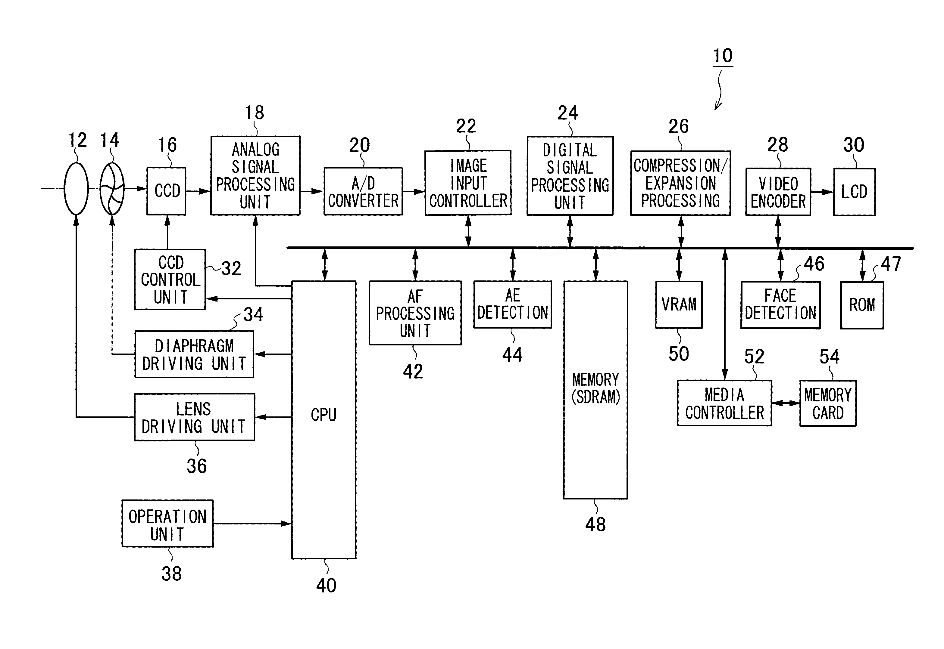
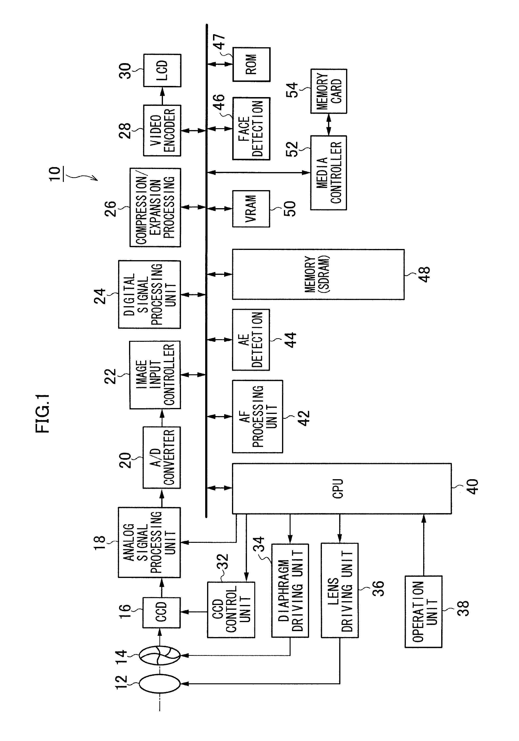
[0083]The stereoscopic imaging apparatus 10 according to a first embodiment of the present invention will be described below.

[0084]FIG. 5 illustrates images respectively obtained when a far subject and a near subject are captured.

[0085]While in FIG. 5, a separation amount (a phase difference) between a main image and a sub-image of a main subject (a person in this example) at an in-focus position is zero, there occurs a phase difference between a main image and a sub-image of a subject corresponding to each of a foreground and a background of the main subject.

[0086]The separation amount of the far subject is decreased so that a stereoscopic effect is reduced, as illustrated in a portion (A) of FIG. 5. On the other hand, the separation amount of the near subject is increased so that stereoscopic viewing cannot be performed when beyond a mixing limit, as illustrated in a portion (B) of FIG. 5.

[0087]In the first embodiment of the present invention, an F-number of the diaphragm 14 is co...

second embodiment

[0096]FIG. 7 is a flowchart illustrating a photographing operation of a stereoscopic imaging apparatus 10 according to a second embodiment of the present invention. Steps common to those in the first embodiment illustrated in FIG. 6 are assigned the same step numbers, and hence detailed description thereof is not repeated.

[0097]The second embodiment differs from the first embodiment in that processes in steps S30 and S32 are performed, as illustrated in FIG. 7, in place of the processes in steps S14 and S16 illustrated in FIG. 6.

[0098]In step S30, a CPU 40 calculates an amount of parallax at a corresponding point between a main image and a sub-image, which have been acquired when a shutter button is pressed halfway. The amount of parallax is calculated by finding, based on one of the images (e.g., the main image), a corresponding pixel on the other image (the sub-image). As a method for finding the corresponding pixel, a block matching method, for example, can be used. A parallax ma...

third embodiment

[0110]FIG. 10 is a flowchart illustrating a photographing operation of a stereoscopic imaging apparatus 10 according to a third embodiment of the present invention. Steps common to those in the first embodiment illustrated in FIG. 6 are assigned the same step numbers, and hence detailed description thereof is not repeated.

[0111]The third embodiment differs from the first embodiment in that processes in steps S40 and S42 are performed, as illustrated in FIG. 10, in place of the processes in steps S14 and S16 illustrated in FIG. 6.

[0112]In step S40, a CPU 40 recognizes a main subject within a photographic angle of view based on an image acquired when a shutter button is pressed halfway. A stereoscopic imaging apparatus 10 according to the present embodiment includes a face detection circuit 46 for detecting the face of a person within the photographic angle of view. While the stereoscopic imaging apparatus 10 can recognize a person as a main subject, therefore, it can recognize a main...


PUM


Abstract

A stereoscopic imaging apparatus comprising a single photographic optical system; an image sensor, on which subject images that have passed through different first and second areas in a predetermined direction, respectively, are formed after being pupil-split, photoelectrically converting the subject images that have passed through the first and second areas, respectively, to output a first image and a second image; a diaphragm restricting a light flux incident on the image sensor; a subject information acquiring device acquiring distance information of a subject within a photographic angle of view or a device acquiring an amount of parallax of the subject; and a diaphragm control device controlling an F-number of the diaphragm so that a parallax between the first image and the second image is in a predetermined range based on the acquired distance information of the subject or the acquired amount of parallax of the subject.

Description

BACKGROUND OF THE INVENTION[0001]1. Field of the Invention[0002]The present invention relates to a stereoscopic imaging apparatus, and more particularly, to a technique for forming subject images that have passed through different areas in a horizontal direction of an photographic optical system on image sensors, respectively, to acquire a left viewpoint image and a right viewpoint image.[0003]2. Description of the Related Art[0004]Known as this type of stereoscopic imaging apparatus has conventionally been one including an optical system illustrated in FIG. 18 (National Publication of International Patent Application No. 2009-527007).[0005]The optical system is configured to pupil-split subject images that have passed through different areas in a horizontal direction of a main lens 1 and a relay lens 2 with a mirror 4 and form the pupil-split subject images on image sensors 7 and 8 via imaging lens 5 and 6, respectively.[0006]FIG. 19 illustrates separated states of images formed on...

Claims


Application Information

Patent Timeline
Patent Type & Authority Applications(United States)
IPC IPC(8): H04N13/02H04N13/30
CPCH04N13/30H04N13/211H04N13/218H04N13/296
Inventor AOKI, TAKASHI
Owner FUJIFILM CORP
Why Eureka
Try Eureka