Eureka AIR delivers breakthrough ideas for toughest innovation challenges, trusted by R&D personnel around the world.

Reception device, reception method, and program

Inactive Publication Date: 2013-11-28
SATURN LICENSING LLC
View PDF8 Cites 2 Cited by
  • Summary
  • Abstract
  • Description
  • Claims
  • Application Information

AI Technical Summary

Benefits of technology

The patent text explains a way to improve the reception of information when there is no data transmission in a specific frequency band. The technical effect of this is better performance in situations where data is not being sent.

Problems solved by technology

Attention should be paid, however, to application of a filter since incorrect application of a filter to a desired signal to be received may result in suppression of even the signal to be received and lead to degradation in performance.

Method used


Image

  • Reception device, reception method, and program
  • Reception device, reception method, and program
  • Reception device, reception method, and program

Examples


Embodiment Construction

Example Structure of Reception Device

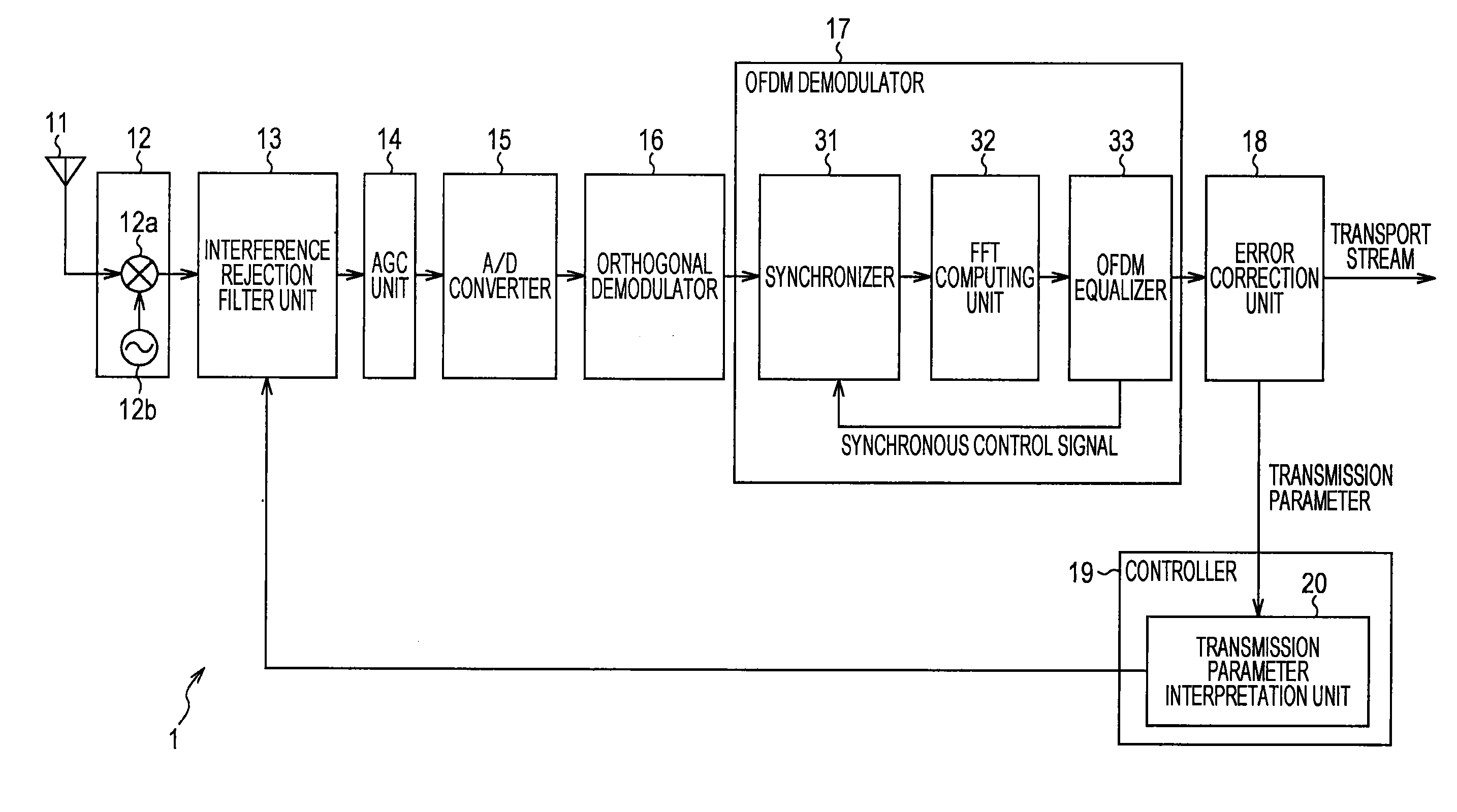
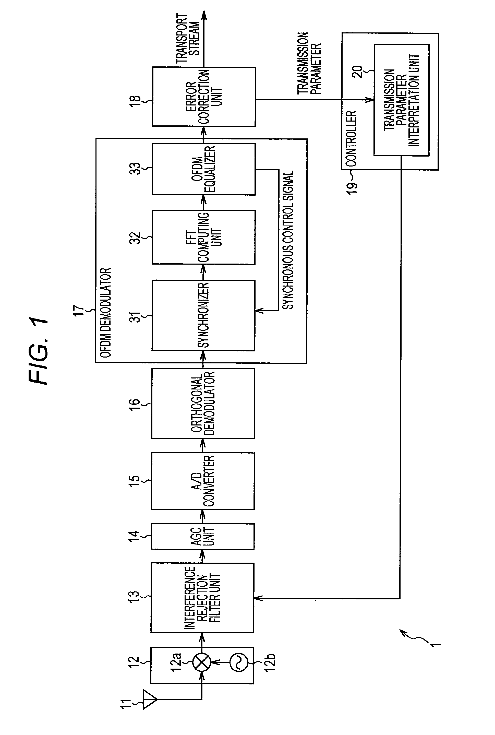
[0031]FIG. 1 shows an example structure of an embodiment of a reception device to which the present technology is applied.

[0032]The reception device 1 of FIG. 1 is an OFDM reception device configured to receive a broadcast wave of an OFDM signal transmitted from a transmission device at a broadcast station that is not shown.

[0033]An antenna 11 receives the transmitted broadcast wave (RF signal) of the OFDM signal and outputs the broadcast wave to a tuner 12.

[0034]The tuner 12 includes an arithmetic operation unit 12a and a local oscillator 12b.

[0035]The arithmetic operation unit 12a multiplies the RF signal from the antenna 11 and a signal from the local oscillator12b together to convert the frequency of the RF signal to obtain an IF (intermediate frequency) signal, and outputs the IF signal to an interference rejection filter unit 13. The local oscillator 12b generates a sinusoidal signal of a predetermined frequency and outputs the signal to t...


PUM


Abstract

The present technology relates to a reception device, a reception method, and a program therefor that enable improvement in reception performance when information on a frequency band in which no data is transmitted is known. The reception device receives a broadcast wave of an OFDM signal transmitted from a transmission device at a broadcast station that is not shown. A transmission parameter interpretation unit acquires band information indicating a “no signal” band contained in transmitted control information. An interference rejection filter unit performs filtering at least when a signal with a level higher than a predetermined level is detected on the basis of the band information from the transmission parameter interpretation unit. The disclosed technology can be applied to a reception device that receives OFDM signals, for example.

Description

TECHNICAL FIELD[0001]The present technology relates to a reception device, a reception method, and a program therefor, and more particularly, to a reception device, a reception method, and a program therefor that enable improvement in reception performance when information on a frequency band in which no data is transmitted is known.BACKGROUND ART[0002]Filtering has often been used as a technique for reducing interference signals. For example, in a case where the interference signals are signals of adjacent channels adjacent to a receiving channel, a band-pass filter or a low-pass filter can be employed to reduce adjacent channel signals. As a result, the influence of adjacent channel signals leaking into the reception frequency band can be suppressed.[0003]Furthermore, in a case where the interference signals are continuous waves (sine waves, for example) existing in a specific frequency range or signals for analog communication existing in the same channel, for example, a notch fi...

Claims


Application Information

Patent Timeline
IPC IPC(8): H04B1/10
CPCH04B1/10H04B1/1036
Inventor YOKOKAWA, TAKASHIGOTO, YUKENTAKAHASHI, HIROO
Owner SATURN LICENSING LLC
Why Eureka
Eureka Blog
Learn More