

Radio-Controlled Timepiece And Control Method For A Radio-Controlled Timepiece
- Summary
- Abstract
- Description
- Claims
- Application Information
AI Technical Summary
Benefits of technology
Problems solved by technology
Method used
Image

Examples
embodiment 1
[0061]A radio-controlled timepiece 1 according to a first preferred embodiment of the invention is described next with reference to the accompanying figures.
[0062]Configuration of the Radio-Controlled Timepiece 1
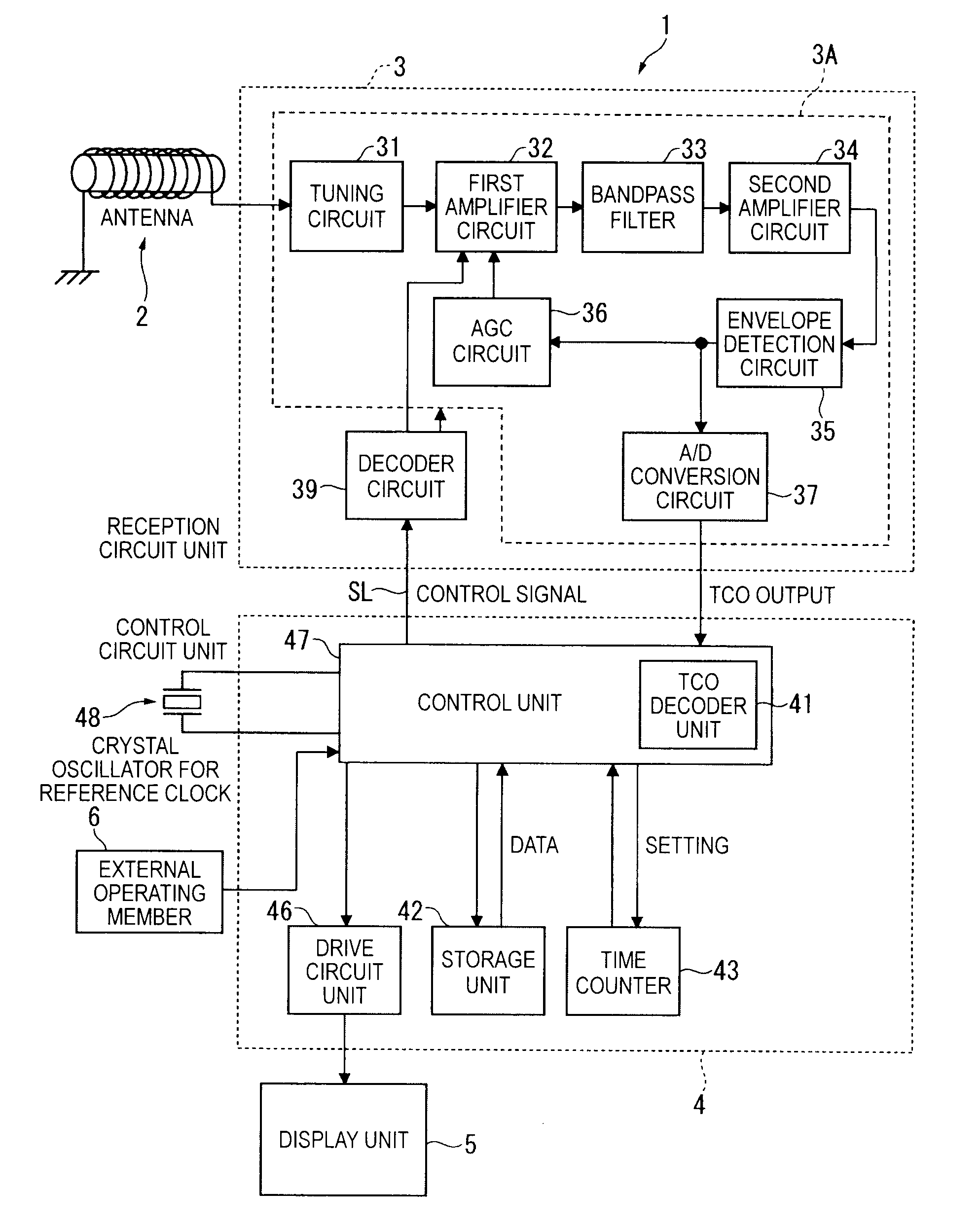
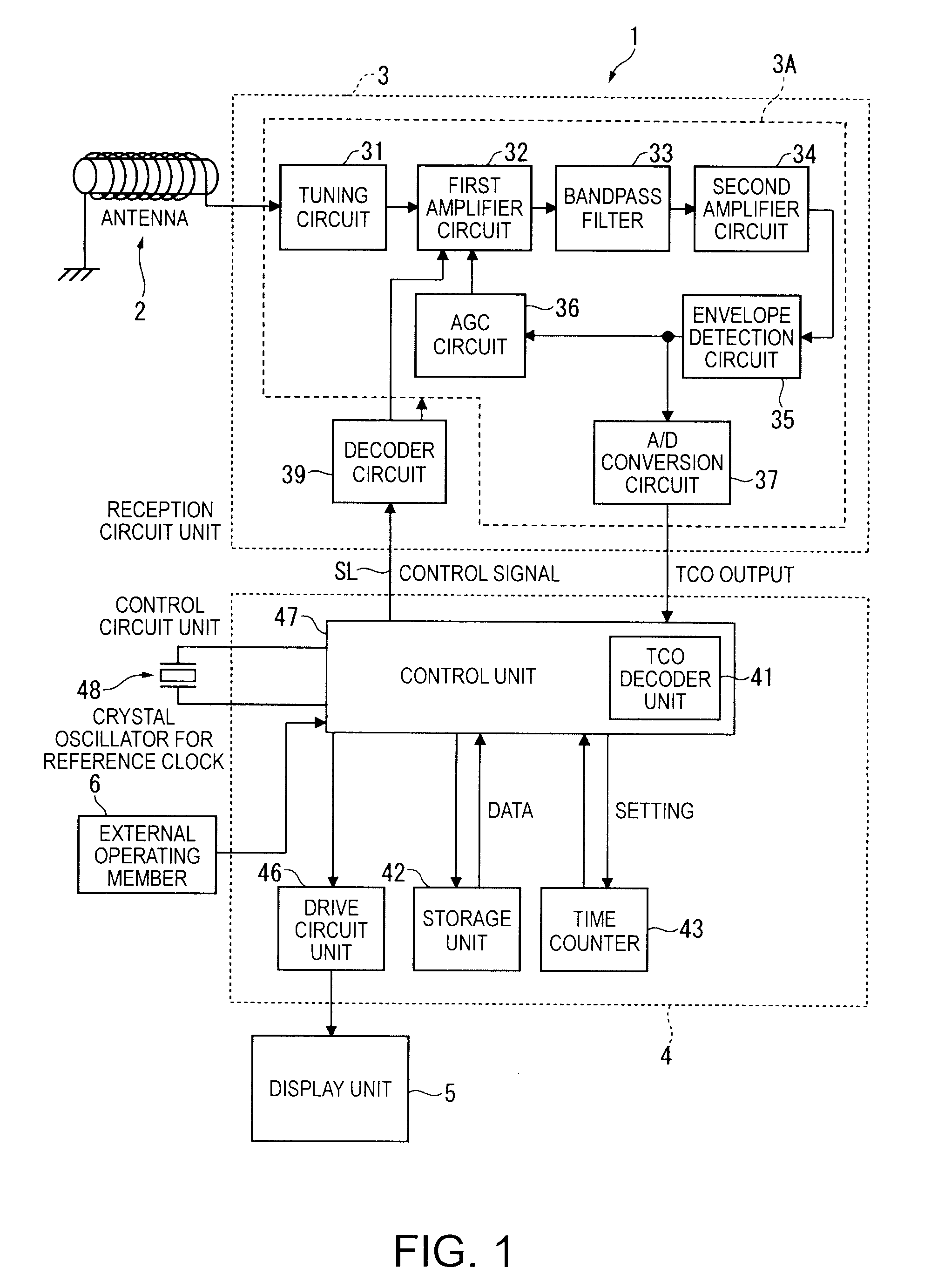
[0063]As shown in FIG. 1 the radio-controlled timepiece 1 has an antenna 2 as a reception unit, a reception circuit unit 3, a control circuit unit 4, a display unit 5, an external operating member 6, and a crystal oscillator 48.
[0064]The antenna 2 receives a long-wave standard time signal (simply “standard time signal” below) and passes the received standard time signal to the reception circuit unit 3.
[0065]The reception circuit unit 3 demodulates the standard time signal received by the antenna 2, and outputs the resulting TCO (time code out) signal to the control circuit unit 4. The reception circuit unit 3 is described in detail further below.
[0066]The control circuit unit 4 decodes the input TCO and generates the time data, and sets the time of the time counter 43 based ...
embodiment 2
[0174]A second embodiment of the invention is described next with reference to the flow chart in FIG. 10 and FIG. 11 and the timing chart in FIG. 12. Note that parts that are the same or similar in any of the embodiments described herein are identified by the same reference numbers and further description thereof is simplified or omitted.
[0175]The first embodiment described above selects the normal reception mode or high sensitivity reception mode for each time code unit in one cycle of the standard time signal, that is, in the one minute (60 second) reception period. This second embodiment of the invention differs by selecting the normal reception mode or high sensitivity reception mode in the one-second period in which 1-bit of information is received.
[0176]Note also that this second embodiment differs from the first embodiment only in the method whereby the control unit 47 changes the reception mode. The configurations of the reception circuit unit 3 and the control circuit unit ...
embodiment 3
[0215]A third embodiment of the invention selects the high sensitivity reception mode when receiving pulses with a narrow width in the standard time signal as shown in FIG. 13.
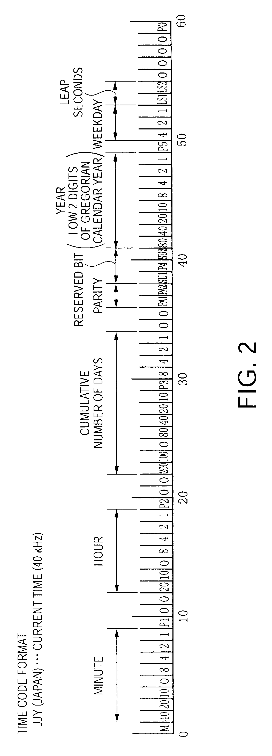
[0216]More specifically, as described above in the first embodiment the standard time signal transmitted in Japan expresses P, 1, and 0 data values using signals with pulse widths of 0.2 second, 0.5 second, and 0.8 second. As shown in FIG. 14, a narrow pulse 101 with a 0.2-second pulse width tends to have a lower amplitude when the rising edge is gradual than a 0.5-second-wide pulse 102 or a 0.8-second-wide pulse 103. As a result, digitizing signals with a narrow pulse width becomes difficult when the signal amplitude is low and the field is weak. More specifically, when the TCO is acquired by digitizing the signal after envelope detection using a predetermined threshold value, the amplitude of pulse 101 in particular is low and the pulse width of the corresponding pulse 101A in the TCO signal becomes shorter,...
PUM
 Abstract
Description
Claims
Application Information