Eureka AIR delivers breakthrough ideas for toughest innovation challenges, trusted by R&D personnel around the world.

Smart antenna system and method for improving receiving performance thereof

Inactive Publication Date: 2016-07-28
ELECTRONICS & TELECOMM RES INST
View PDF11 Cites 10 Cited by
  • Summary
  • Abstract
  • Description
  • Claims
  • Application Information

AI Technical Summary

Benefits of technology

The present invention provides a method for improving the receiving sensitivity of a smart antenna system by tracking a signal source in real time using a plurality of beams. This improves the overall receiving mode without affecting the transceiving system and allows for more accurate signal detection. The invention also includes a method for measuring and comparing the sizes of signals of beam patterns without using a complex digital block. The technical effect of this invention is to enhance the sensitivity and performance of wireless communication systems.

Problems solved by technology

Various paths interfere with wireless communication signals which are transmitted through a channel.
The interference causes signal fading and signal attenuation which lowers a signal to noise ratio (SNR) as a result, thereby deteriorating a quality of a received signal.
The multiple antenna has an excellent effect to improve a quality of the signal, but since individual antennas are configured by active antennas, the number of RF transceivers is undesirably increased in proportion to the number of antennas.
First, complex channel modeling and a digital process are required to achieve beam forming to increase the reception sensitivity. The method has a long computing time, so that it is difficult to track a signal source which varies in real time and a load for a digital block is increased. Therefore, it is difficult to maximize an effect of reducing the RF chain.
Second, since it is required to complete beam tracking during an idle time to change a beam pattern of an antenna, the computing time is increased as the number of parasitic antennas is increased, so that it is difficult to exactly estimate a direction of the beam. Further, since the RF chain cannot receive the signal while finding the beam, the reception efficiency is reduced. Specifically, in spite of detecting an optimal direction, there may be an additional problem in that the sensitivity of the signal is ironically reduced during a computation period to track the other direction.
Third, a reactance load to form a pattern of a beam generally uses a capacitance between both ends of a variable diode element or a phase shift technology of a parasitic antenna using a phase shifter, but in order to implement a desired capacitance, the variable diode needs to be applied with high power voltage of 10 V or larger and the minute adjustment of the phase shifter is not possible for each, and an insertion loss is large, so that it is difficult to apply the antenna of the related art to the system.

Method used


Image

  • Smart antenna system and method for improving receiving performance thereof
  • Smart antenna system and method for improving receiving performance thereof
  • Smart antenna system and method for improving receiving performance thereof

Examples


Embodiment Construction

[0042]Hereinafter, the most preferred exemplary embodiments of the present invention will be described in detail with reference to the accompanying drawings so that those skilled in the art may easily carry out the technical spirit of the present invention.

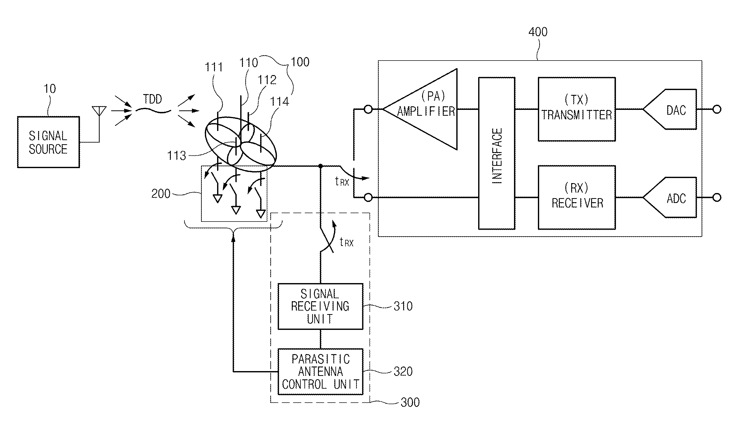
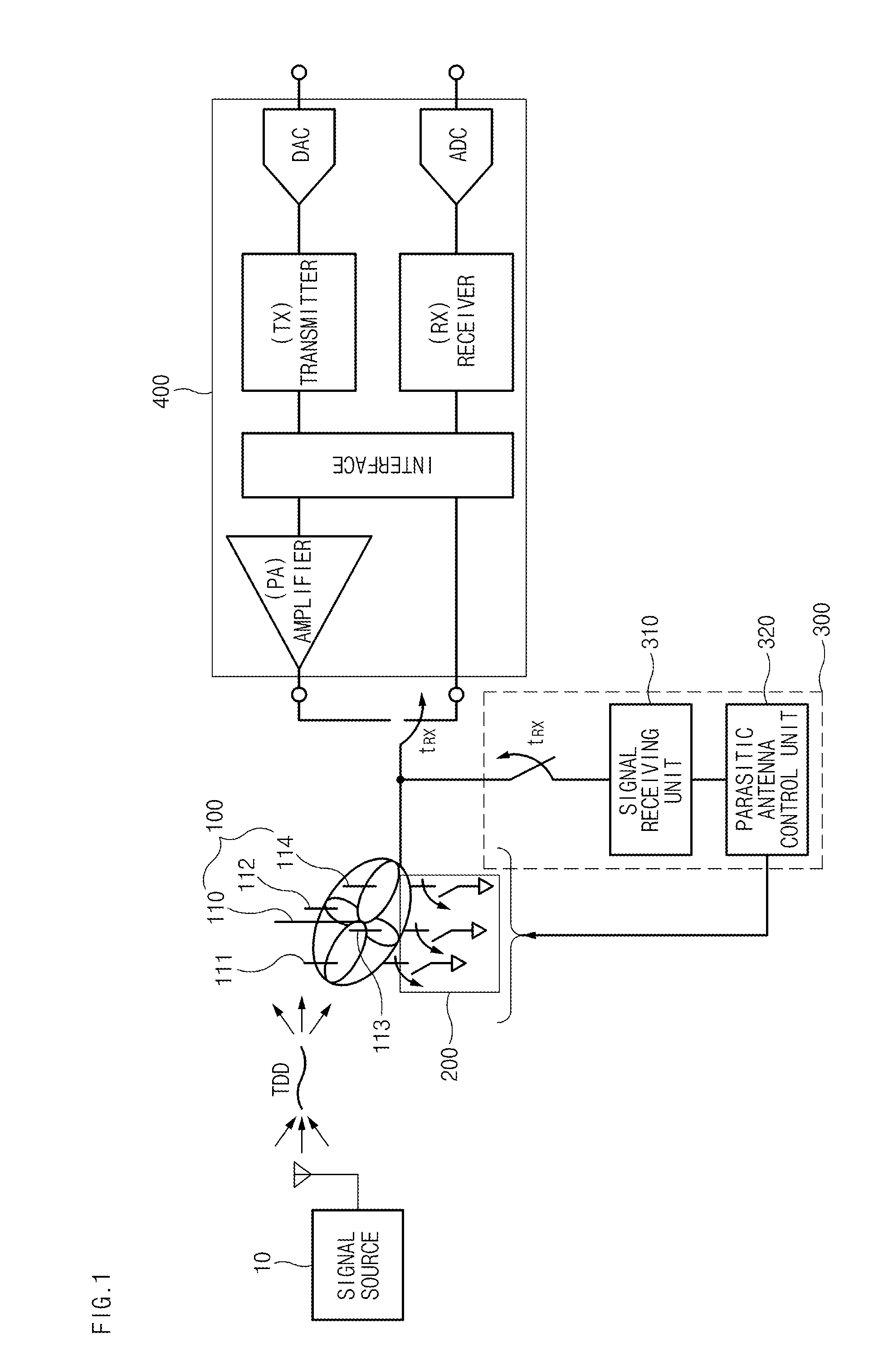
[0043]The present invention suggests a technique which compares strengths of received signals to form a beam toward a largest signal without using a complex mathematical model such as a channel model of the related art or a beam forming algorithm, thereby improving sensitivity of the signal. That is, when a reactance load of the parasitic antenna at which a characteristic of the received signal, such as a signal to noise ratio (SNR) or an adjacent channel leakage ratio (ACLR), is maximized is adjusted, the direction of the beam is changed and thus a direction of the beam which has optimal reception sensitivity may be determined.

[0044]Hereinafter, exemplary embodiments of the present invention will be specifically described with re...


PUM


Abstract

A smart antenna system according to an exemplary embodiment of the present invention including a beam forming antenna which includes an active antenna and a plurality of parasitic antennas, the system including: a reactance load which is connected to the parasitic antenna; a transceiver which transmits and receives a signal to the beam forming antenna; and an antenna adjusting block which tracks a signal source in real time using a plurality of beam patterns having the largest signal size and forms a beam in a direction having the largest signal size.

Description

CROSS-REFERENCE TO RELATED APPLICATIONS[0001]This application claims priority to and the benefit of Korean Patent Application No. 10-2015-00122242 filed in the Korean Intellectual Property Office on Jan. 26, 2015, the entire contents of which are incorporated herein by reference.TECHNICAL FIELD[0002]The present invention relates to a smart antenna system and a method for improving a receiving performance thereof, and more particularly, to a technique which adjusts an antenna beam by adjusting a load of a parasitic antenna in accordance with a signal so as to increase sensitivity of a signal.BACKGROUND ART[0003]Various paths interfere with wireless communication signals which are transmitted through a channel. The interference causes signal fading and signal attenuation which lowers a signal to noise ratio (SNR) as a result, thereby deteriorating a quality of a received signal.[0004]Therefore, methods which receive the received signals through several antennas (for example, an array ...

Claims


Application Information

Patent Timeline
IPC IPC(8): H04B7/06H04B7/08H01Q3/26
CPCH04B7/0615H04B7/0848H01Q3/26H01Q19/32H04B7/086H04B7/0814H04B7/088
Inventor CHO, YOUNG KYUNPARK, BONG HYUKOH, JUNG HOONLEE, JUNG NAMJO, GWEON DO
Owner ELECTRONICS & TELECOMM RES INST
Why Eureka
Eureka Blog
Learn More