Bone fixation screw and method

Active Publication Date: 2013-11-28
J M LONGYEAR MFG LLC
View PDF23 Cites 21 Cited by
  • Summary
  • Abstract
  • Description
  • Claims
  • Application Information

AI Technical Summary

Benefits of technology

[0004]In one form, the invention is directed to a bone screw fixation assembly comprising a bone screw portion, a torque stabilizer portion, and a compressor lock portion. After placement of a guidewire, and boring with surgical drills, the bone screw portion comprising distally placed bone screw threads is fed over the guidewire and seated into the head of the femur at a predetermined location. A tubular torque stabilizer portion comprising a second positioner is advanced upon a first positioner on the bone screw portion therein eliminating rotational motion therebetween. Torsional stops projecting from the

Problems solved by technology

Hip fractures, for example, are a common p

Method used


Image

  • Bone fixation screw and method
  • Bone fixation screw and method
  • Bone fixation screw and method

Examples


Embodiment Construction

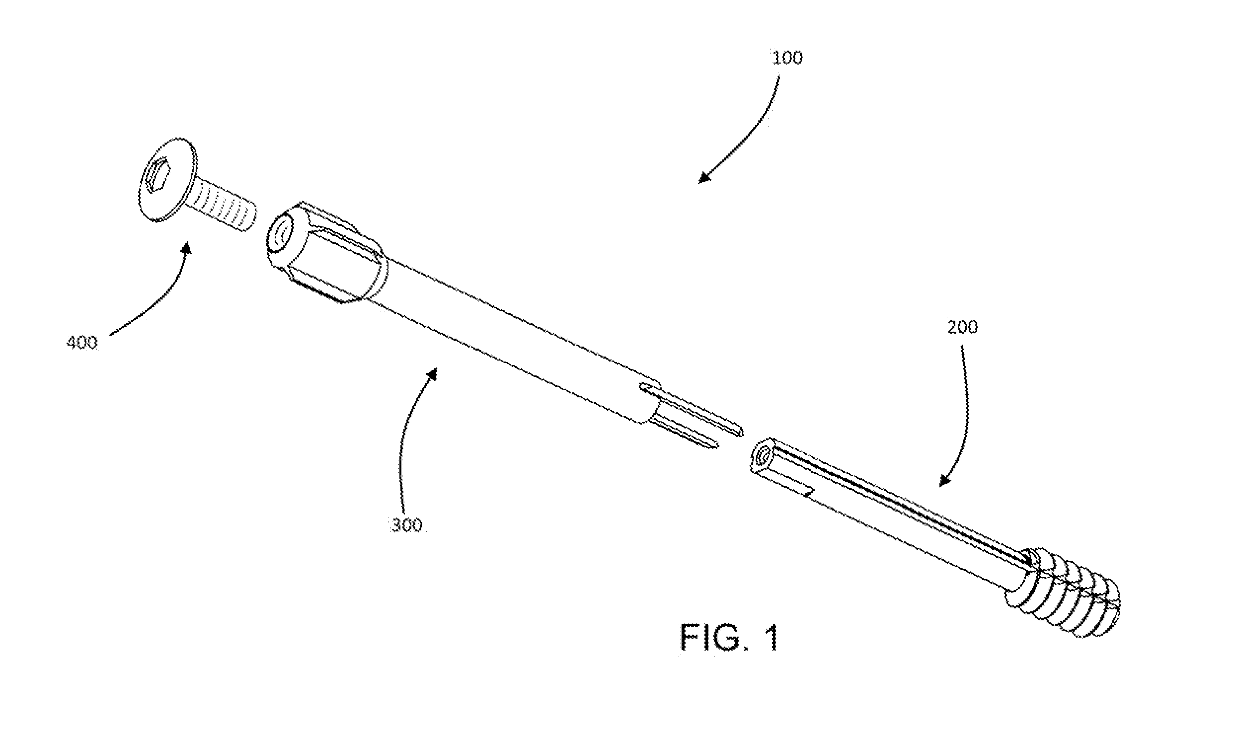
[0037]In a preferred embodiment illustrated in FIG. 1, the fixation screw assembly 100 comprises a bone screw portion 200, a torque stabilizer portion 300, and a compressor lock portion 400. Although not necessary, it is preferred that one or more parts of the screw assembly 100 is cannulated to pass a guide wire for guidance of the assembly to a predetermined bone site location.

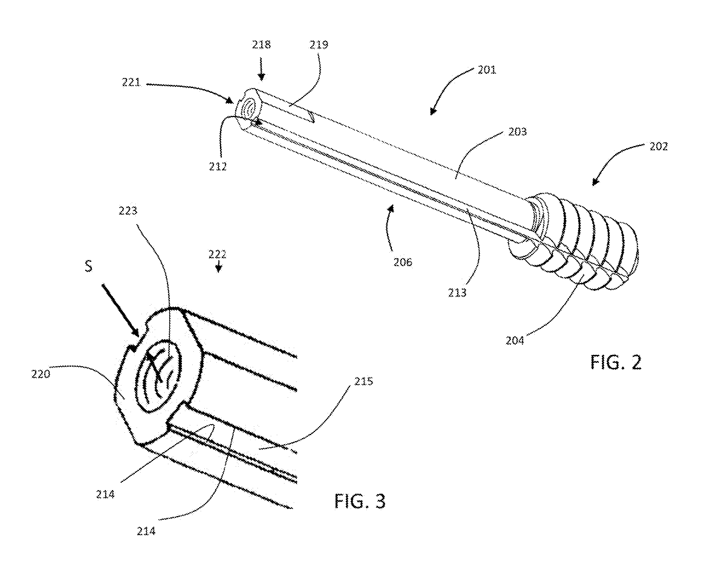
[0038]In the preferred embodiment of the device, the bone screw portion 200 illustrated in FIGS. 2-5 comprises a cannulated elongate body 201 with central axis ‘A’. Positioned on the distal end 202 over the outer surface 203 of the elongate body 201 are several bone screw threads 204 with a tapered lead-in 205. Proximal along the elongate body 201 from the threads 204 is a shank portion 206 of the bone screw 200 and a continuation of the elongate body outer surface 203.

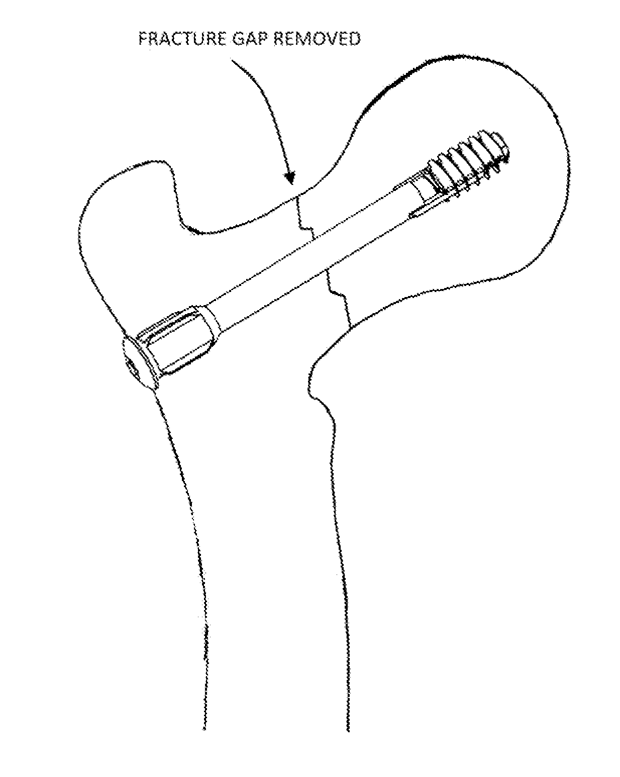
[0039]The bone screw threads in this embodiment are configured to seat within the softer cortical bone of the head of the femur. For this rea...


PUM


Abstract

A screw device for compressing and fixing together a proximal and distal bone part along a surgical axis comprising: a bone screw portion comprising an elongate body inscribed with bone screw threads at a leading end of an outer surface of said body; an elongate tubular torque stabilizer portion for spanning said bone parts and comprising one or more torsion stops to engage each bone part to limit rotational movement between the bone parts and a translation stop on said torque stabilizer to seat against a portion of the proximal bone to limit translation of said torque stabilizer portion along the surgical axis; and a compressor lock portion engaging the bone screw portion and torque stabilizer portion to draw said bone screw portion proximally along the surgical axis toward said translation stop therein compressing said one parts together.

Description

[0001]The present application is a utility patent application that claims priority to U.S. Provisional Application Ser. No. 61 / 650,440, filed on May 22, 2012.BACKGROUND[0002]The present invention relates generally to the stabilization of adjacent bone portions and particularly for the stabilization of fractures. Hip fractures, for example, are a common problem that is often challenging to remedy. Femoral neck fractures of the hip typically involve the narrow neck between the shaft of the femur and the round head. The device disclosed may be used to secure and compress the bone segments on each side of the fracture site.SUMMARY OF THE INVENTION[0003]Disclosed herein is a bone screw assembly for stabilizing and compressing together two or more bone parts. In its preferred form this assembly is well suited for stabilizing femoral neck fractures utilizing a minimal incision at the operational site.[0004]In one form, the invention is directed to a bone screw fixation assembly comprising ...

Claims


Application Information

Patent Timeline
IPC IPC(8): A61B17/74
CPCA61B17/742A61B17/7233A61B17/844A61B17/863A61B17/8635A61B17/8685A61B2017/681A61B2017/8655
Inventor SONGER, MATTHEWSANDSTROM, JASONKORHONEN, FRANCIS
Owner J M LONGYEAR MFG LLC
Why Eureka
Try Eureka