A filter assembly for separating oil from compressed gas and compressor comprising such filter assembly

A filter assembly, a technology for compressing gas, used in membrane filters, dispersed particle filtration, liquid fuel engines, etc., can solve problems such as increasing the complexity and cost of liquid separation filters

Pending Publication Date: 2019-01-25
ATLAS COPCO AIRPOWER NV
View PDF8 Cites 0 Cited by
  • Summary
  • Abstract
  • Description
  • Claims
  • Application Information

AI Technical Summary

Problems solved by technology

[0013] However, even changing the material of the seal or its shape does not solve the problems posed by the rotation of such a filter about its axis and will only increase the complexity and cost associated with liquid separation filters

Method used


Image

  • A filter assembly for separating oil from compressed gas and compressor comprising such filter assembly
  • A filter assembly for separating oil from compressed gas and compressor comprising such filter assembly
  • A filter assembly for separating oil from compressed gas and compressor comprising such filter assembly

Examples


Embodiment Construction

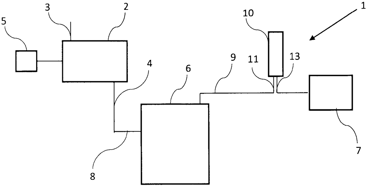
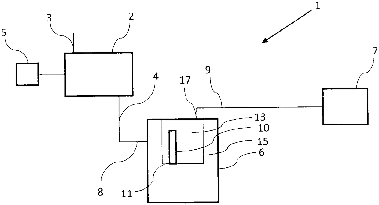
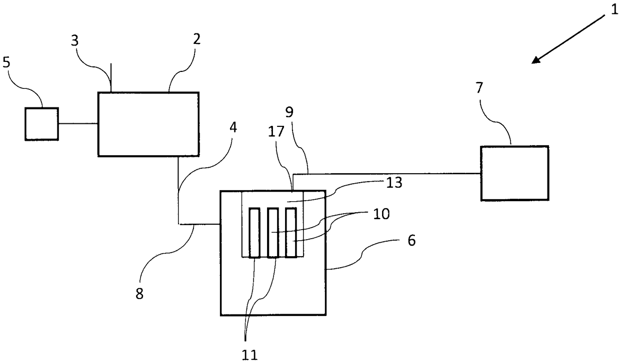
[0041] figure 1 A compressor 1 is shown comprising a compressor element 2 with a gas inlet 3 and a compressed gas outlet 4 . The compressor element 2 is driven by a constant speed motor or a variable speed motor 5 .

[0042] In the context of the present invention, compressor 1 should be understood as the entire compressor arrangement, including compressor element 2 , all typical connecting pipes and valves, the casing of compressor 1 and possibly a motor 5 driving compressor element 2 .

[0043] In the context of the present invention, a compressor element 2 is to be understood as a compressor element housing in which the compression process takes place by means of a rotor or by a reciprocating movement.

[0044] Furthermore, the compressor element 2 may be selected from the group consisting of screws, teeth, jaws, scrolls, rotating vanes, centrifuges, pistons.

[0045] back now figure 1 , the compressor 1 further comprises a separation vessel 6 arranged on the compressed ...


PUM


Abstract

The present invention is directed to a filter assembly comprising a housing (15) and a filter cartridge (10), whereby the housing comprises (15) a housing inlet (16) and a housing outlet (17), the filter cartridge (10) comprising a filter inlet (11) fluidly connected to the housing inlet (16) and a filter element (12) provided between a top cap (18) and a bottom cap (19), whereby the bottom cap (19) comprises the filter inlet (11), whereby the top cap (18) and the bottom cap (19) create a circular or predominantly circular guiding system, and whereby the bottom cap (19) farther comprises a first part (19a) that receives the filter element (12) and a second part (19b) that is connected with a mating surface (20) of the housing (5), characterised in that the second part (19b) comprises a first circular section (21a) and a second section (21b); and that the first section has another shape than the second section (21b), such that the bottom cap (19) cannot rotate in relation to the matingsurface (20).

Description

technical field [0001] The present invention relates to a filter assembly comprising a housing and a filter element for separating liquid from compressed gas, the filter element being disposed within the housing, the housing comprising: [0002] - a housing inlet adapted to be fluidly connected to a compressed gas outlet and [0003] - the housing outlet from which the purge gas is recovered, [0004] The cartridge includes a filter inlet fluidly connected to the housing inlet and a filter element disposed between a top cover and a bottom cover also forming part of the cartridge, the bottom cover including the filter inlet, wherein The top cover and the bottom cover form a circular or predominantly circular guide system for mounting the filter element, and wherein the bottom cover further includes a first portion that receives the filter element and is connected to a second portion of the mating surface of the housing. Background technique [0005] Liquid separation filte...

Claims


Application Information

Patent Timeline
Patent Type & Authority Applications(China)
IPC IPC(8): B01D46/24F04B39/16
CPCB01D46/2411F04B39/16B01D46/0005B01D46/2414B01D2201/296B01D2201/4046B01D2201/4076B01D2265/021B01D2265/026B01D46/2407B01D46/00B01D46/24B01D2273/28F04D29/701B01D46/58
Inventor K·A·L·马滕斯S·M·R·劳伦特J·A·L·威利肖沃尔
Owner ATLAS COPCO AIRPOWER NV
Why Eureka
Try Eureka