Lancet device

Inactive Publication Date: 2013-11-28
ASAHI POLYSLIDER CO LTD +1
View PDF7 Cites 3 Cited by
  • Summary
  • Abstract
  • Description
  • Claims
  • Application Information

AI Technical Summary

Benefits of technology

[0028]The lancet device according to the invention has a straight pathway of the pricking needle during the pricking action. That is, the pricking needle moves straightly in the pricking direction and then straightly retracts without wobbling. As a result, the pain of the pricked subject (i.e., a person from whom blood is taken) can be largely relieved upon pricking. This means that the pain felt by the person to be pricked (i.e., the subject of the blood sampling) can be largely reduced at the time of the pricking. While not wishing to be bound by any theory, the reduced pain is believed to be attributed to a reduction of “adverse hollowing or scratching phenomenon of the pricked portion by the wobbling needle”.
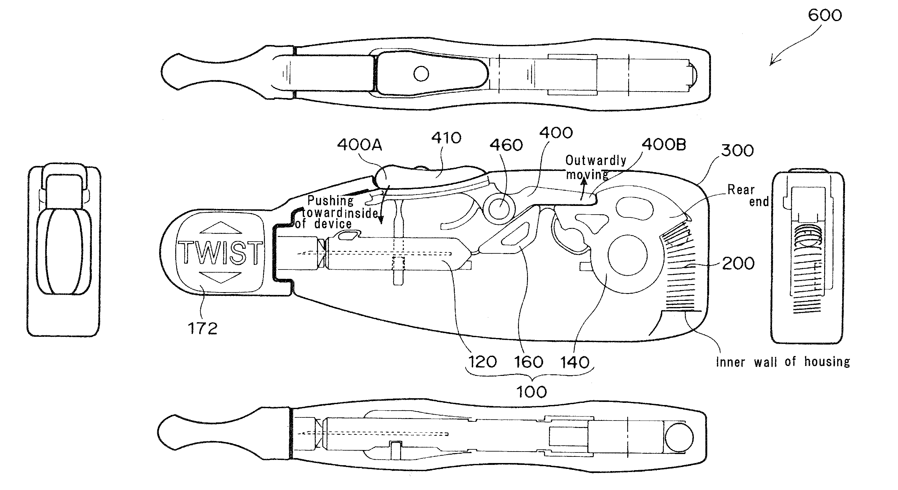
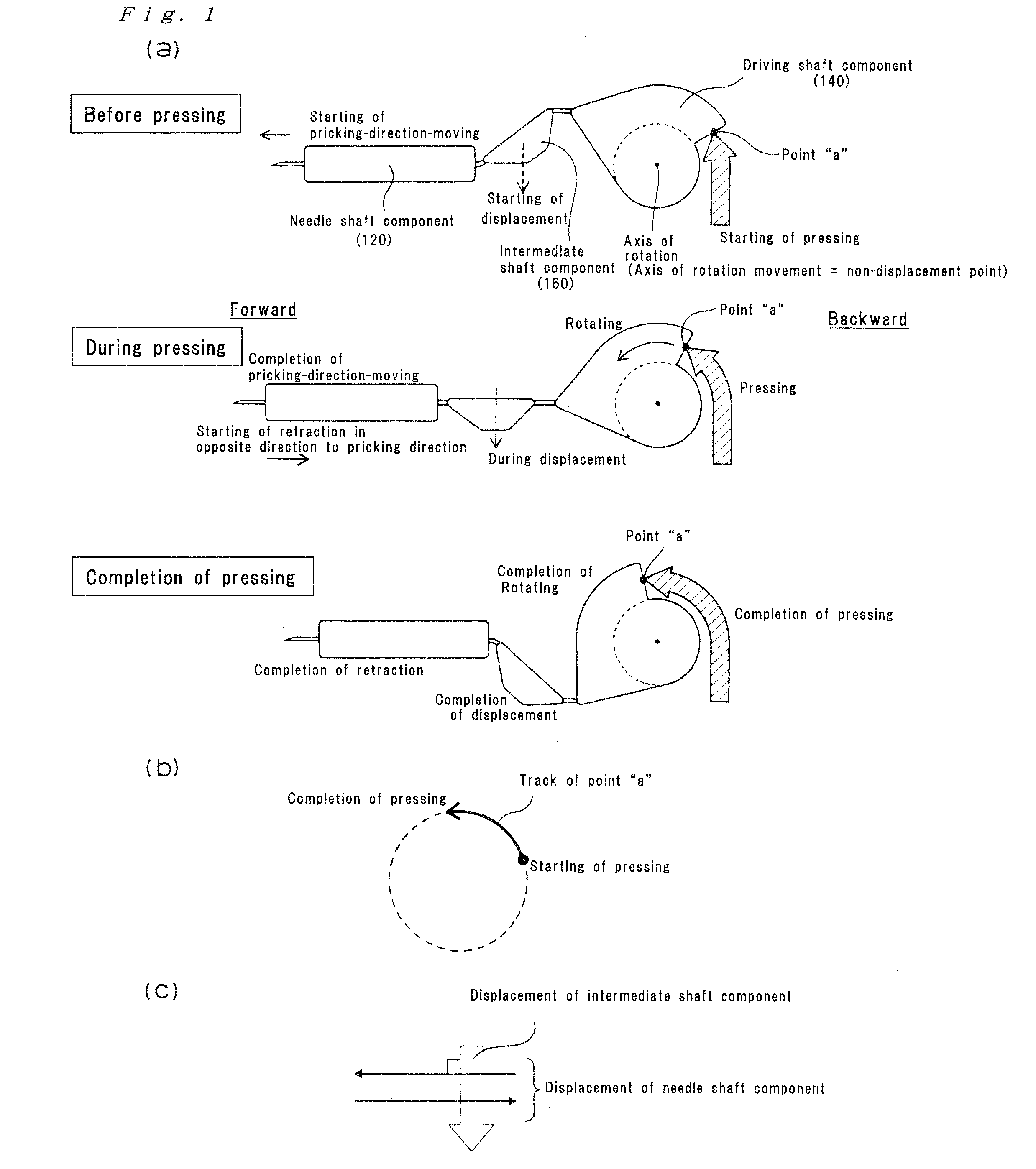
[0029]In particular, the lancet device of the invention has a large force for moving the needle shaft component in the pricking direction. The reason for this is that the moving of needle shaft component in the pricking direction is caused by the intermediate shaft component displaced due to the rotation of the driving shaft component. Because of such large force, even while the needle shaft component is in strong abutment against the guide rails, the needle shaft component can slide in the pricking direction, which appropriately ensures the linearity of the needle shaft component. That is, the needle shaft component of the lancet device can forcefully move in the pricking direction, even when the needle shaft component is largely pressed against the guide rail, causing a large sliding resistance between the needle shaft component and the guide rails. This means that the lancet device according to the invention appropriately achieves the linearity of the needle shaft component, the linearity being based on the guide rails.
[0032]A slight space is provided between the pricking needle and the guide.
[0033]In contrast to such conventional lancet device, the invention makes it possible to smoothly move the needle shaft component in the pricking direction because of a large moving force of the needle shaft component even while the needle shaft component is strongly being pressed against the guide rail, which sufficiently exhibits the linearity based on the guide rail. From another viewpoint, the lancet device according to the

Problems solved by technology

This will result in a wound of the body through which the patient's blood may enter the body (i.e.

Method used


Image

  • Lancet device
  • Lancet device
  • Lancet device

Examples


Example

[0146]The device shown in FIG. 5 was used as the lancet device of the invention (Example 1), whereas a “plunger lancet device equipped with a stick-like plunger” was used as a prior art device of Comparative Example (Comparative Example 1: Prior art device “A”, Comparative Example 2: Prior art device “B”).

[0147]The results are shown in the following Table 1 as well as FIG. 42.

TABLE 1ItemProtruding length of needleWobbling of tip of needleDevicePrior artPrior artDevice of Presentdevice “A”device “B”Prior artPrior artInvention(Comparative(ComparativeDevice of Presentdevice “A”device “B”(Example 1)Example 1)Example 2)Invention(Comparative(ComparativeSetting forSetting forSetting forSetting for(Example 1)Example 1)Example 2)protrudingprotrudingprotrudingprotrudingSetting forSetting forSetting forSetting forlength oflength oflength oflength ofprotrudingprotrudingprotrudingprotrudingneedle: 1 mmneedle: 1.5 mmneedle: 1.5 mmneedle: 1.8 mmlength oflength oflength oflength ofFrontLateralFront...


PUM


Abstract

There is provided a lancet device comprising a pricking part and a pressing part. In the lancet device of the present invention, the pricking part is comprised of a needle shaft component equipped with a pricking needle, a driving shaft component, and an intermediate shaft component therebetween, the needle shaft component, the driving shaft component and the intermediate shaft component being connected to each other via a joint component. When a pricking operation is performed, the driving shaft component of the pricking part is at least partly rotated by being pressed by a pressing action of the pressing part, and thereby the intermediate shaft component of the pricking part is displaced causing the needle shaft component to move in a pricking direction.

Description

TECHNICAL FIELD[0001]The present invention relates to a pricking device. More specifically, the present invention relates to a lancet device which is used for taking a sample of body fluid such as blood.BACKGROUND OF THE INVENTION[0002]In order to measure a blood sugar level of a patient with diabetes, it is required to take a sample of the blood from the patient. The small amount of the taken blood may be enough. Thus, a pricking device capable of taking a small amount of blood is used to measure the blood sugar level. The pricking device is generally composed of a lancet (see, for example, U.S. Pat. No. 5,385,571) and an injector. The lancet has a pricking needle capable of puncturing a predetermined region of the patient's body. The injector has a function of launching the lancet toward the predetermined region. The pricking device is set up for use by loading the lancet into the injector. Then, the lancet is launched toward the predetermined region by means of a plunger of the i...

Claims


Application Information

Patent Timeline
IPC IPC(8): A61B5/151
CPCA61B5/15117A61B5/150022A61B5/150297A61B5/150412A61B5/150549A61B5/150618A61B5/150717A61B5/15113A61B5/1513A61B5/15144A61B5/1519A61B5/150259
Inventor SAEKI, HIDEAKISEKI, KAZUHARUABE, TERUYUKI
Owner ASAHI POLYSLIDER CO LTD
Why Eureka
Try Eureka