
X-ray imaging apparatus and control method therefor

a technology of x-ray imaging and control method, which is applied in the field of x-ray imaging apparatus, can solve the problems of increased workflow needed for x-ray imaging, increased etc., and achieve the effect of reducing workflow for performing x-ray imaging and alleviating subject pain due to breast compression

Active Publication Date: 2015-09-03
SAMSUNG ELECTRONICS CO LTD
View PDF1 Cites 11 Cited by
  • Summary
  • Abstract
  • Description
  • Claims
  • Application Information

AI Technical Summary

Benefits of technology

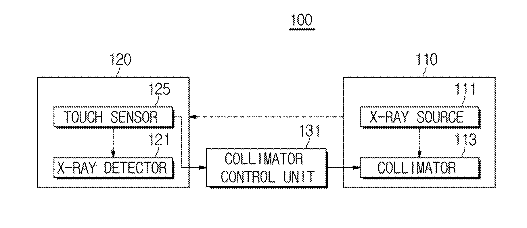
The present invention provides an X-ray imaging apparatus and a control method for it that can measure the region of a compressed breast using a touch sensor and control the collimator to align the X-ray emission region with the measured region of the breast. This reduces the workflow for X-ray imaging and alleviates pain caused by breast compression. The method also involves generating X-rays, emitting them through the controlled collimator, detecting them with the X-ray detector, and removing errors caused by the touch sensor from the X-ray data of the object.

Problems solved by technology

A radiologist manually adjusts an emission region of X-rays in a state in which a breast of a subject is compressed, and thus, workflow needed for X-ray imaging is increased and subject pain due to breast compression are also increased.

Method used


Image

  • X-ray imaging apparatus and control method therefor
  • X-ray imaging apparatus and control method therefor
  • X-ray imaging apparatus and control method therefor

Examples


Embodiment Construction

[0042]Reference will now be made in detail to the embodiments of the present invention, examples of which are illustrated in the accompanying drawings, wherein like reference numerals refer to like elements throughout.

[0043]Hereinafter, embodiments of the present invention will be described in detail with reference to the accompanying drawings.

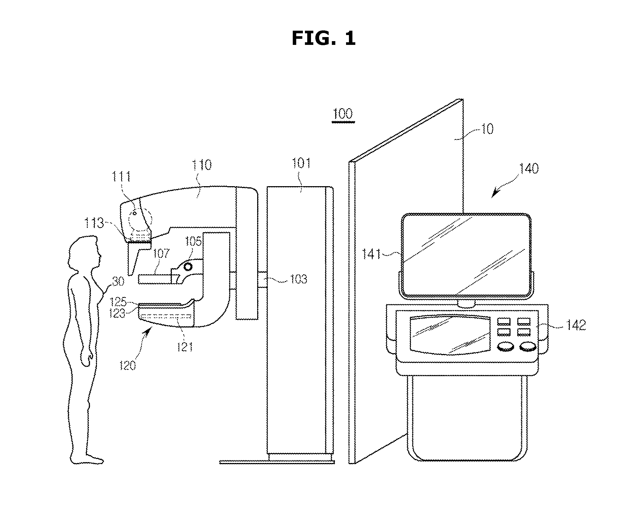
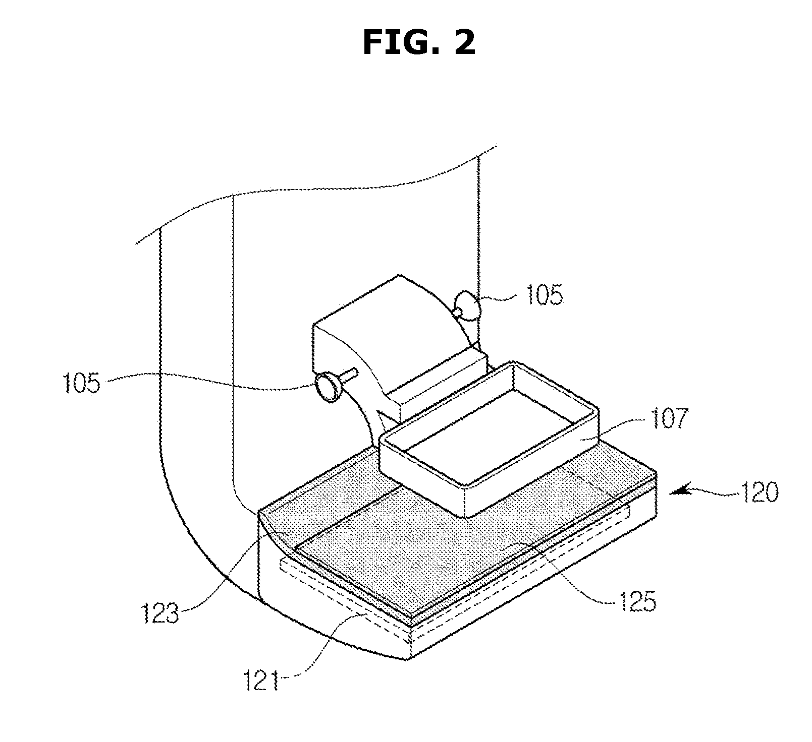
[0044]FIG. 1 is an overall exterior view of an X-ray imaging apparatus 100 according to an embodiment of the present invention. FIG. 2 is an enlarged view of an X-ray detection unit equipped with a touch sensor 125.

[0045]The X-ray imaging apparatus 100 according to an embodiment of the present invention may perform imaging of breasts. An X-ray imaging apparatus for mammography is configured to emit X-rays in a state in which a breast is compressed, in terms of characteristics of breasts with mammary gland tissues and adipose tissues. Hereinafter, the configuration of the X-ray imaging apparatus 100 will be described in detail with reference to...


PUM


Abstract

Disclosed herein are an X-ray imaging apparatus and a control method therefor in which a region of a compressed breast is measured by a touch sensor and a collimator is controlled such that an X-ray emission region corresponds to the measured region of a compressed breast, whereby workflow for performing X-ray imaging may be reduced and subject pain due to breast compression may be alleviated. The X-ray imaging apparatus includes an X-ray source to generate X-rays and irradiate an object with the generated X-rays, a collimator to adjust an emission region of the X-rays generated from the X-ray source, an X-ray detector to detect X-rays having passed through the object to acquire X-ray data, a touch sensor disposed above the X-ray detector, a compression paddle to compress the object placed on the touch sensor, and a collimator control unit to calculate location and size of the compressed object based on an output value of the touch sensor and control the collimator based on calculation results.

Description

BACKGROUND[0001]1. Field[0002]Embodiments of the present invention relate to an X-ray imaging apparatus to generate an X-ray image by passing X-rays through an object and a control method therefor.[0003]2. Description of the Related Art[0004]X-ray imaging apparatuses are devices to irradiate an object with X-rays and acquire an image of the interior of the object using X-rays having passed through the object. The penetration of X-rays varies according to properties of materials constituting the object, and thus, an internal structure of the object may be imaged by detecting the intensity of X-rays having passed through the object.[0005]Among these X-ray imaging apparatus, a mammography apparatus examines breasts as an object. Breasts contain mammary gland tissues and adipose tissues, and thus, X-ray imaging needs to be performed in a state in which a breast placed between an X-ray source and an X-ray detector is compressed using a compression paddle in order to acquire an X-ray imag...

Claims


Application Information

Patent Timeline
Patent Type & Authority Applications(United States)
IPC IPC(8): A61B6/00A61B6/06A61B6/04
CPCA61B6/542A61B6/502A61B6/5258A61B6/06A61B6/0414A61B6/4035H01L2924/0002H01L2924/00A61B6/544A61B5/103A61B5/107A61B5/053A61B5/0531A61B5/6887A61B5/708A61B6/469A61B6/5252A61B6/545G21K1/046G01B7/32G01B7/003B25J9/1694H01J35/025G06G7/04H01L23/642H01L23/647
Inventor KIM, JONG PILBAEK, SO DAM
Owner SAMSUNG ELECTRONICS CO LTD
Learn More