

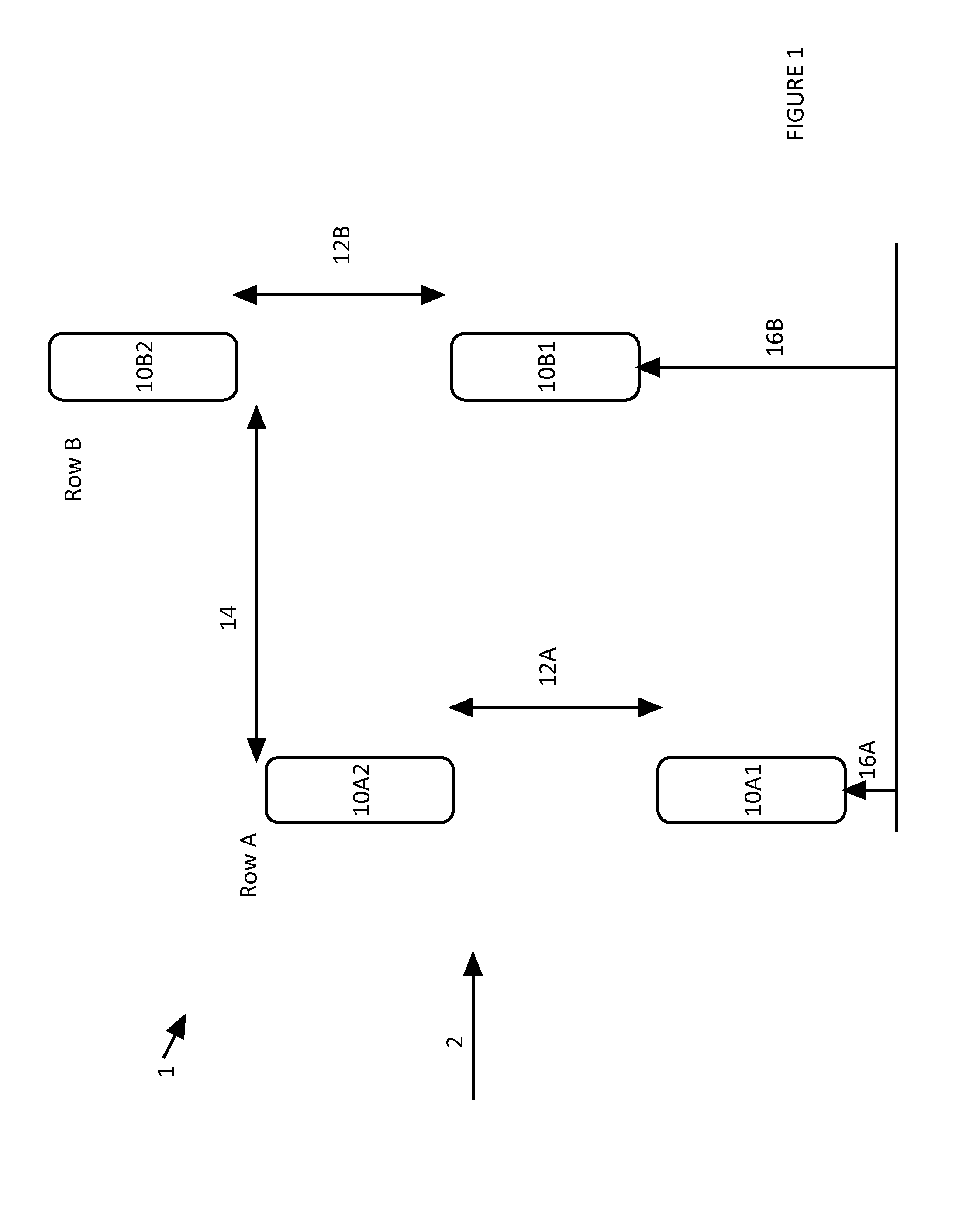
Water current turbine arrangements
- Summary
- Abstract
- Description
- Claims
- Application Information
AI Technical Summary
Benefits of technology
Problems solved by technology
Method used
Image

Examples
Embodiment Construction
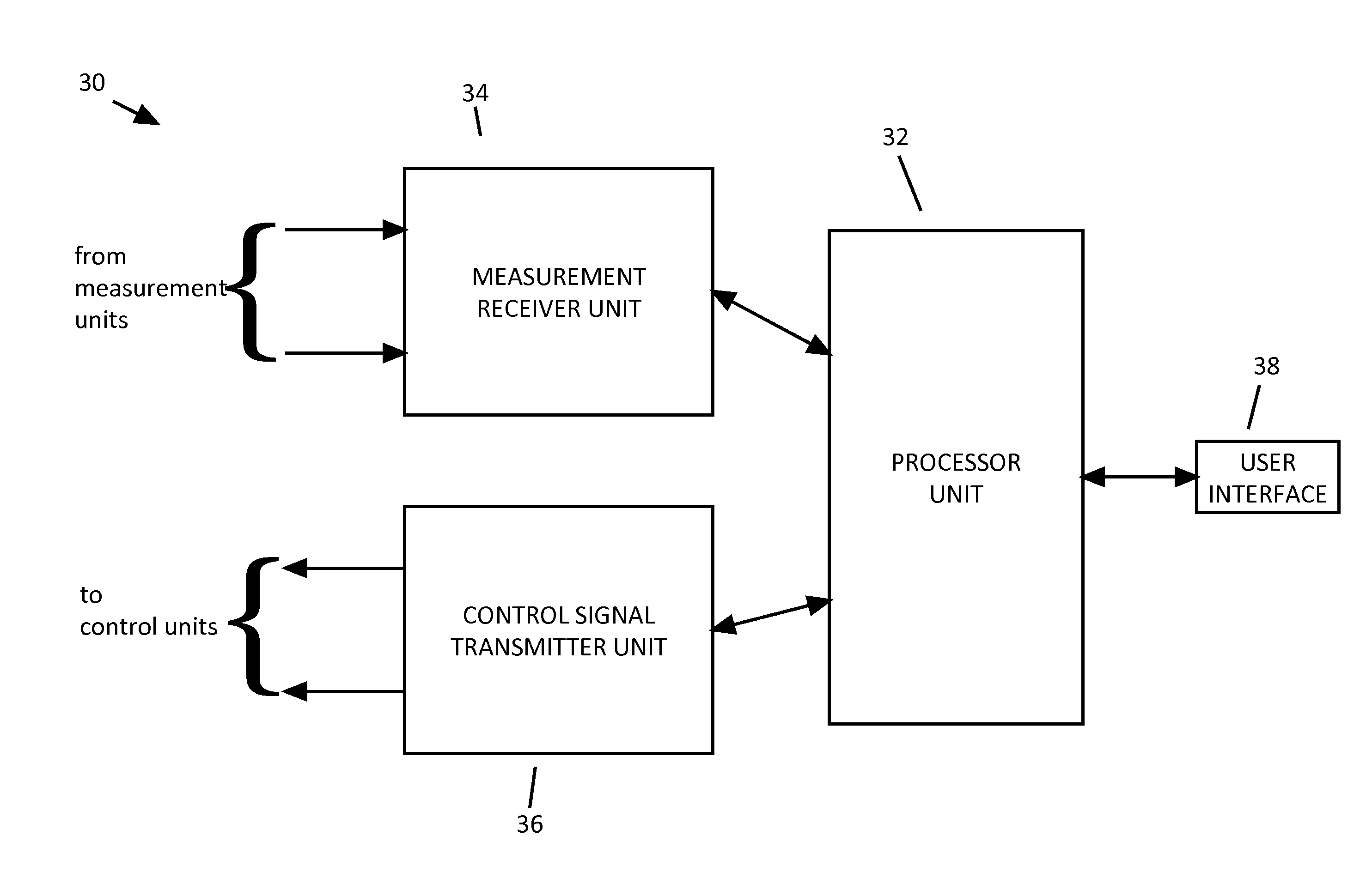
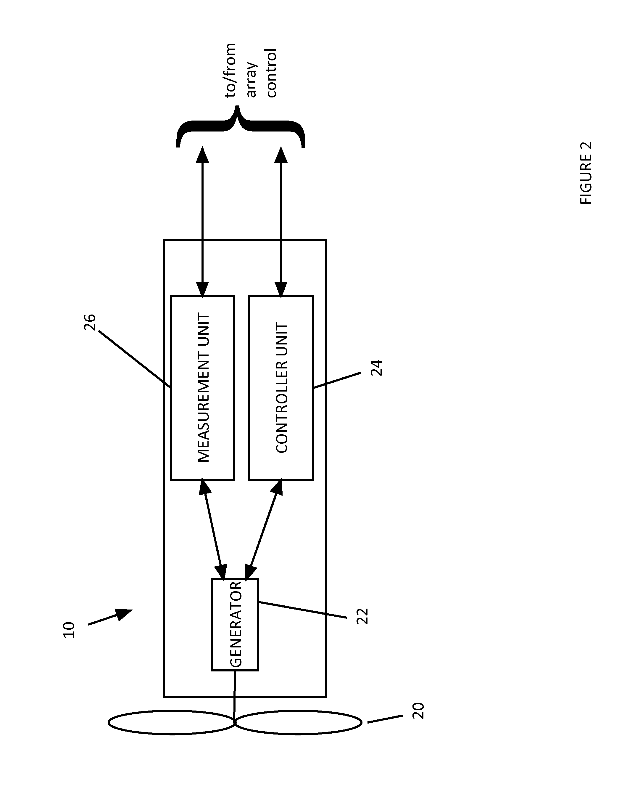
[0029]FIG. 2 is a block diagram of a water current turbine 10 embodying one aspect of the present invention, for use in a water current turbine array, such as that illustrated in FIG. 1. The water current turbine 10 includes a rotor assembly 20, which is arranged to be driven by the water current. The rotor assembly 20 rotates a shaft that transmits power to an electrical generator 22, which operates to generate electricity for supply to the power grid.
[0030]The water current turbine 10 is provided with a controller unit 24, which operates to control the power generation characteristics of the electrical generator 22, so that the generator provides a required electrical power output. A measurement unit 26 is provided for monitoring the generator 22, and for providing measurement information regarding the power generating characteristics of the generator 22, in particular, and of the water current turbine 10 in general.
[0031]The controller unit 24 and the measurement unit 26 are oper...
PUM
 Abstract
Description
Claims
Application Information