Projector and control method for the projector

a control method and projector technology, applied in the field of projectors, can solve the problems of user operation, user power supply operation, and the inability of the projection system to receive the operation of a user and opera

Active Publication Date: 2013-12-05
SEIKO EPSON CORP
View PDF5 Cites 17 Cited by
  • Summary
  • Abstract
  • Description
  • Claims
  • Application Information

AI Technical Summary

Benefits of technology

[0024]According to the aspects of the invention, in a configuration in which a projector performs projection in cooperation with another projector, when an operation state of the other proje...

Problems solved by technology

However, when the projector that receives commands cannot perform normal operation because, for example, some abnormality occurs in the projector, even if the oth...

Method used


Image

  • Projector and control method for the projector
  • Projector and control method for the projector
  • Projector and control method for the projector

Examples


Embodiment Construction

[0029]An embodiment to which the invention is applied is explained below with reference to the accompanying drawings.

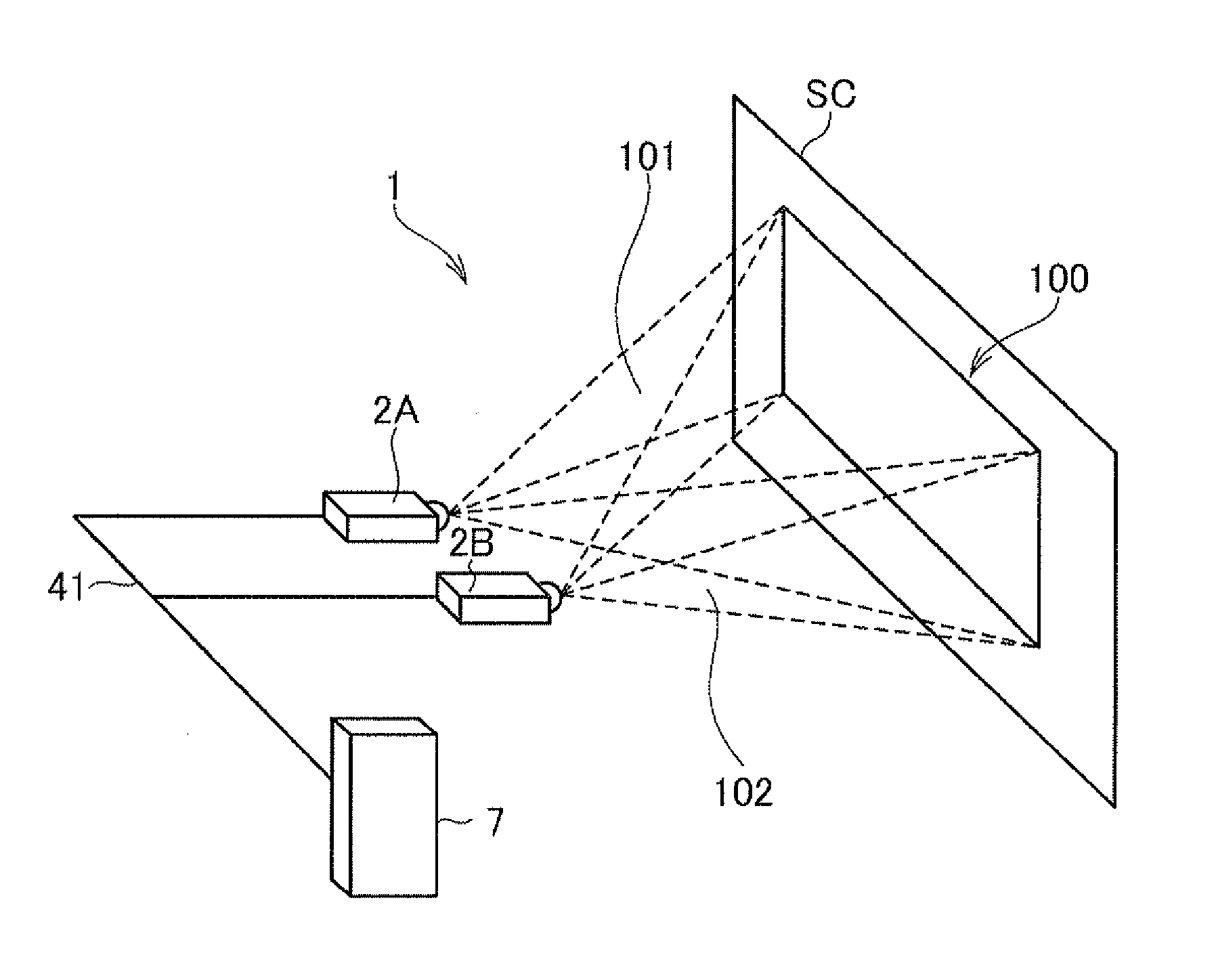
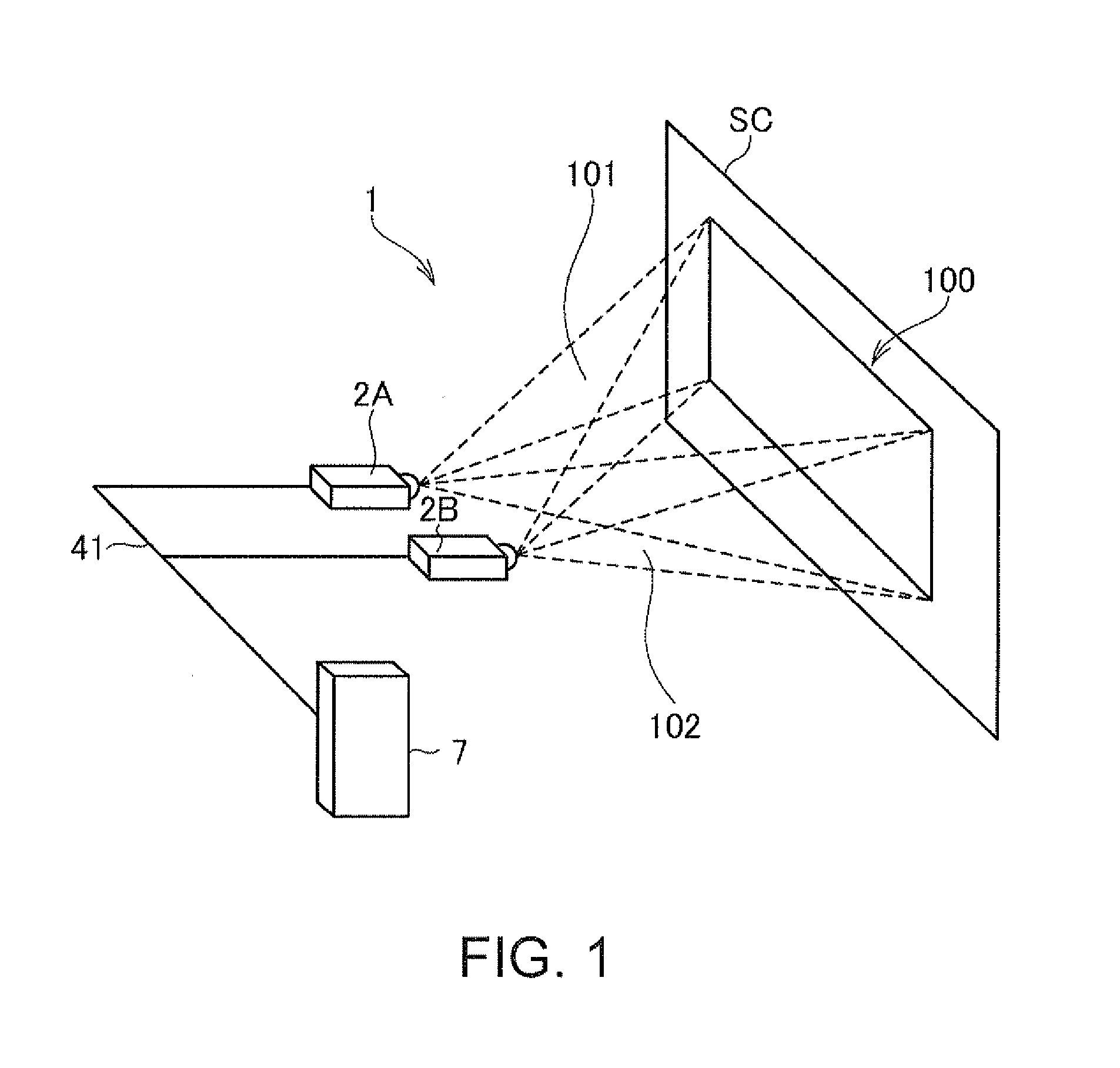
[0030]FIG. 1 is a diagram showing a schematic configuration of a projection system 1 according to the embodiment of the invention.

[0031]In the projection system 1, a projector (another projector) 2A and a projector 2B are set side by side. Stack display is performed to superimpose projected images 101 and 102 projected by the two projectors 2A and 2B on a screen SC (a projection surface). In FIG. 1, a configuration in which the projectors 2A and 2B are set side by side horizontally is shown as an example. The projectors 2A and 2B may be set side by side vertically. The projectors 2A and 2B may be set to be placed on the floor in front of the screen SC (placed on a table) or may be set to be suspended from the ceiling.

[0032]The projectors 2A and 25 are connected to an image output apparatus 7 via an image transmission cable 41. The projectors 2A and 25 respectively pro...


PUM


Abstract

A projector that performs projection in cooperation with another projector, the projector including a determining unit configured to determine an operation state of the other projector and a control unit configured to control the projector to shift to, when the determining unit determines that the operation state of the other projector is not a normal operation state, a limited operation mode for limiting execution of at least a part of functions.

Description

CROSS-REFERENCE[0001]The entire disclosure of Japanese Patent Application No. 2012-127089 filed on Jun. 4, 2012, which is hereby incorporated by reference in its entirety.BACKGROUND[0002]1. Technical Field[0003]The present invention relates to a projector that projects an image on a projection surface and a control method for the projector.[0004]2. Related Art[0005]There has been known a projection system that projects an identical image in a stacked manner using a plurality of projectors to thereby improve the brightness of a projected image projected on a projection surface (see, for example, JP-A-2000-338941 (Patent Literature 1)). In the projection system of this type, the plurality of projectors are serially connected. One projector that receives commands representing all the projectors transmits a necessary command to the other projectors. In general, the projection system performs control for disabling user operation for the projectors other than the projector that receives c...

Claims


Application Information

Patent Timeline
IPC IPC(8): G03B21/14
CPCG03B21/142H04N9/3147H04N9/3185
Inventor ARUGA, TADANORIYASUDA, YUTAKAKATAHIRA, TORU
Owner SEIKO EPSON CORP
Why Eureka
Try Eureka