
Circuit device, physical quantity detection device, electronic apparatus, and vehicle

Active Publication Date: 2017-09-28
SEIKO EPSON CORP
View PDF3 Cites 1 Cited by
  • Summary
  • Abstract
  • Description
  • Claims
  • Application Information

AI Technical Summary

Benefits of technology

This patent describes a way to detect when the main clock signal fails in a circuit device. This is important because it means that the device can still operate even if the main clock signal is failing. The patent also mentions that the device can use an alternative clock signal that is not affected by changes in the frequency of the vibrator. This means that the device can have sufficient processing speed for various tasks, such as control processing and digital signal detection. In summary, the patent provides a solution to ensure the reliability and efficiency of the circuit device.

Problems solved by technology

In addition, since the defect diagnosis circuit cannot output error information of the circuit device, an external device cannot exactly know the presence or absence of an error of the circuit device, and thus there is a possibility that the external device cannot perform an operation according to the error.
In control processing or digital signal processing performed by the control circuit, there is a possibility that a processing speed is not sufficient at a driving frequency of the vibrator.
In a detection process (for example, an A / D conversion process) or digital signal processing which is performed by the detection circuit, there is a possibility that a processing speed is not sufficient at a driving frequency of the vibrator.

Method used


Image

  • Circuit device, physical quantity detection device, electronic apparatus, and vehicle
  • Circuit device, physical quantity detection device, electronic apparatus, and vehicle
  • Circuit device, physical quantity detection device, electronic apparatus, and vehicle

Examples


Embodiment Construction

[0042]Hereinafter, a preferred embodiment of the invention will be described in detail. Meanwhile, the present embodiment to be described below does not unduly limit the content of the invention described in the appended claims, and not all of the features described in the present embodiment are essential for solving means of the invention.

1. Configuration

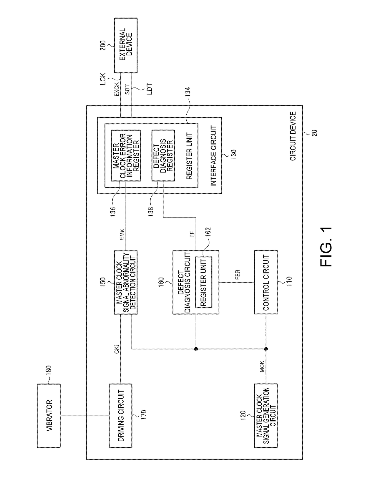
[0043]FIG. 1 illustrates an example of a configuration of a circuit device 20 according to this embodiment. The circuit device 20 includes a master clock signal generation circuit 120, a master clock signal failure detection circuit 150, a defect diagnosis circuit 160, an interface circuit 130, a control circuit 110 (processing circuit), and a driving circuit 170. The circuit device 20 is configured as, for example, an integrated circuit device.

[0044]The master clock signal generation circuit 120 generates a master clock signal MCK which is a clock signal for driving the circuit device 20 (synchronously operating, for example, a lo...


PUM


Abstract

A circuit device includes a driving circuit that generates a clock signal by oscillating a vibrator, a master clock signal generation circuit that generates a master clock signal, and a master clock signal failure detection circuit that detects a failure of the master clock signal. The master clock signal failure detection circuit detects the failure of the master clock signal on the basis of an error detection clock signal, which is the clock signal from the driving circuit, and the master clock signal.

Description

BACKGROUND[0001]1. Technical Field[0002]The present invention relates to a circuit device, a physical quantity detection device, an electronic apparatus, a vehicle, and the like.[0003]2. Related Art[0004]Defect diagnosis circuits may be provided in circuit devices in order to diagnose various defects in the circuit devices. An external device, such as a CPU, reads out error information, which is output by the defect diagnosis circuit, through an interface circuit of the circuit device and performs an operation based on the error information. Related art of the defect diagnosis circuit includes, for example, a technique disclosed in JP-A-2012-181677. In JP-A-2012-181677, a defect diagnosis circuit performs defect diagnosis of a driving circuit driving a physical quantity transducer of a physical quantity detection device and a detection circuit detecting a physical quantity on the basis of a detection signal from the physical quantity transducer, and an interface circuit outputs erro...

Claims


Application Information

Patent Timeline
IPC IPC(8): G01C25/00G01C19/5776
CPCG01C19/5776G01C25/00G01R31/2836H03L7/083H03L7/099
Inventor NAKAJIMA, KIMINORIMAKI, KATSUHIKO
Owner SEIKO EPSON CORP
Learn More