Brake bleeder wrench

a bleeder wrench and wrench technology, applied in the field of brake bleeder wrenches, can solve the problems of repositioning the wrench, inefficient brake operation, and complicating the bleeding process of turning the bleeder valv

Active Publication Date: 2020-04-16
A&E DESIGN
View PDF2 Cites 1 Cited by
  • Summary
  • Abstract
  • Description
  • Claims
  • Application Information

AI Technical Summary

Benefits of technology

[0008]A pawl is provided to select engagement direction of the teeth on the socket wheel, so that the tool is capable of reversible operation without repositioning the tool onto the bleeder valve during operation.

Problems solved by technology

However, the presence of air, which is comparatively compressible, in a brake line results in inefficient operation of the brakes.
The manual repositioning of the hex wrench complicates the bleeding process of turning the bleeder valve in tight quarters.

Method used


Image

  • Brake bleeder wrench
  • Brake bleeder wrench
  • Brake bleeder wrench

Examples


Embodiment Construction

[0019]Although the disclosure hereof is detailed and exact to enable those skilled in the art to practice the invention, the physical embodiments herein disclosed merely exemplify the invention which may be embodied in other specific structures. While the preferred embodiment has been described, the details may be changed without departing from the invention, which is defined by the claims.

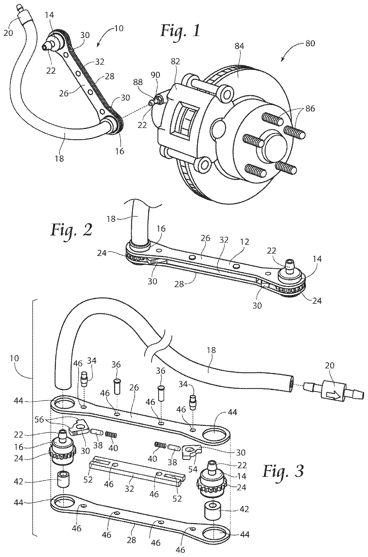
[0020]Referring now to FIG. 1, a perspective view of a typical brake system 80 is shown. A driver pushes a brake pedal (not shown), initiating a sequence that results in hydraulic pressure being applied through a brake line (not shown) containing brake fluid (not shown), to brake caliper pistons (not shown) inside the brake caliper 82. This process engages brake pads (not shown) to frictionally engage with rotor or disc 84 which is coupled to a car wheel (not shown) carried by wheel studs 86, all well known in the art.

[0021]A brake fluid line carries brake fluid from a brake fluid reservoir under ...


PUM


Abstract

A ratcheting brake bleeder wrench is provided which sealingly couples to a bleed valve. The brake bleeder wrench has an internal fluid passageway which allows egress of fluid from a hydraulic brake system. The ratcheting brake bleeder wrench is used to open the bleed valve, allowing egress of fluid, remains in place during the bleeding operation, and reverses direction upon completion of bleeding to tighten the bleed valve back into sealing relationship with the hydraulic brake system.

Description

BACKGROUND OF THE INVENTION[0001]Vehicles are equipped with brakes to stop or slow when desired. A driver pushes a brake pedal, initiating a sequence that results in hydraulic pressure being applied through a brake line containing brake fluid, to brake caliper pistons, which exert brake pads to slow the vehicle as the brake pads compress against a rotating rotor.[0002]Because brake fluid is not compressible, brake fluid efficiently transfers force into hydraulic pressure allowing the efficient operation of the brake system. However, the presence of air, which is comparatively compressible, in a brake line results in inefficient operation of the brakes.[0003]Air can enter the brake lines in various ways, such as degraded seals. Alternatively, when brake line fluid is changed, as proper maintenance requires, air enters the hydraulic system and the air must be removed. When brake lines are replaced, they initially contain air, but then receive brake fluid as brake fluid is introduced i...

Claims


Application Information

Patent Timeline
Patent Type & Authority Applications(United States)
IPC IPC(8): B25B13/48B25B27/00B60T17/22
CPCB25B13/463B25B27/0035B60T17/222B25B13/48B25B13/04F16D2125/16
Inventor DAHL, VINCENTKUZMIC, JEFFREY J.
Owner A&E DESIGN
Why Eureka
Try Eureka