Valve Device having a Movement Element which is Cylindrical at least in Sections

Active Publication Date: 2013-12-05
ROBERT BOSCH GMBH
View PDF11 Cites 2 Cited by
  • Summary
  • Abstract
  • Description
  • Claims
  • Application Information

AI Technical Summary

Benefits of technology

[0010]One embodiment of the invention makes provision for the number N to be three. A guide element having three contact portions and three connection portions can be pressed inwards in a stable manner and results in a particularly small deformation of the guide recess. Such a guide element can further be produced in a simple and inexpensive manner.
[0011]The invention is particularly advantageous if recesses are provided between the connection portions when viewed in the peripheral direction. It is thereby possible to provide in the guide element axial openings which are necessary for the operation of the valve device and through which, for example, fuel can flow. The recesses preferably have a number N which is correspondingly identical to the contact portions and the connection portions and they are also arranged so as to be uniformly distributed in the peripheral direction. In particular, the recesses can be arranged radially between the connection portions—in accordance with the above-described regions of lesser rigidity—so that the guide rece

Problems solved by technology

In addition to the hardness of the component, the guiding play h

Method used


Image

  • Valve Device having a Movement Element which is Cylindrical at least in Sections
  • Valve Device having a Movement Element which is Cylindrical at least in Sections
  • Valve Device having a Movement Element which is Cylindrical at least in Sections

Examples


Example

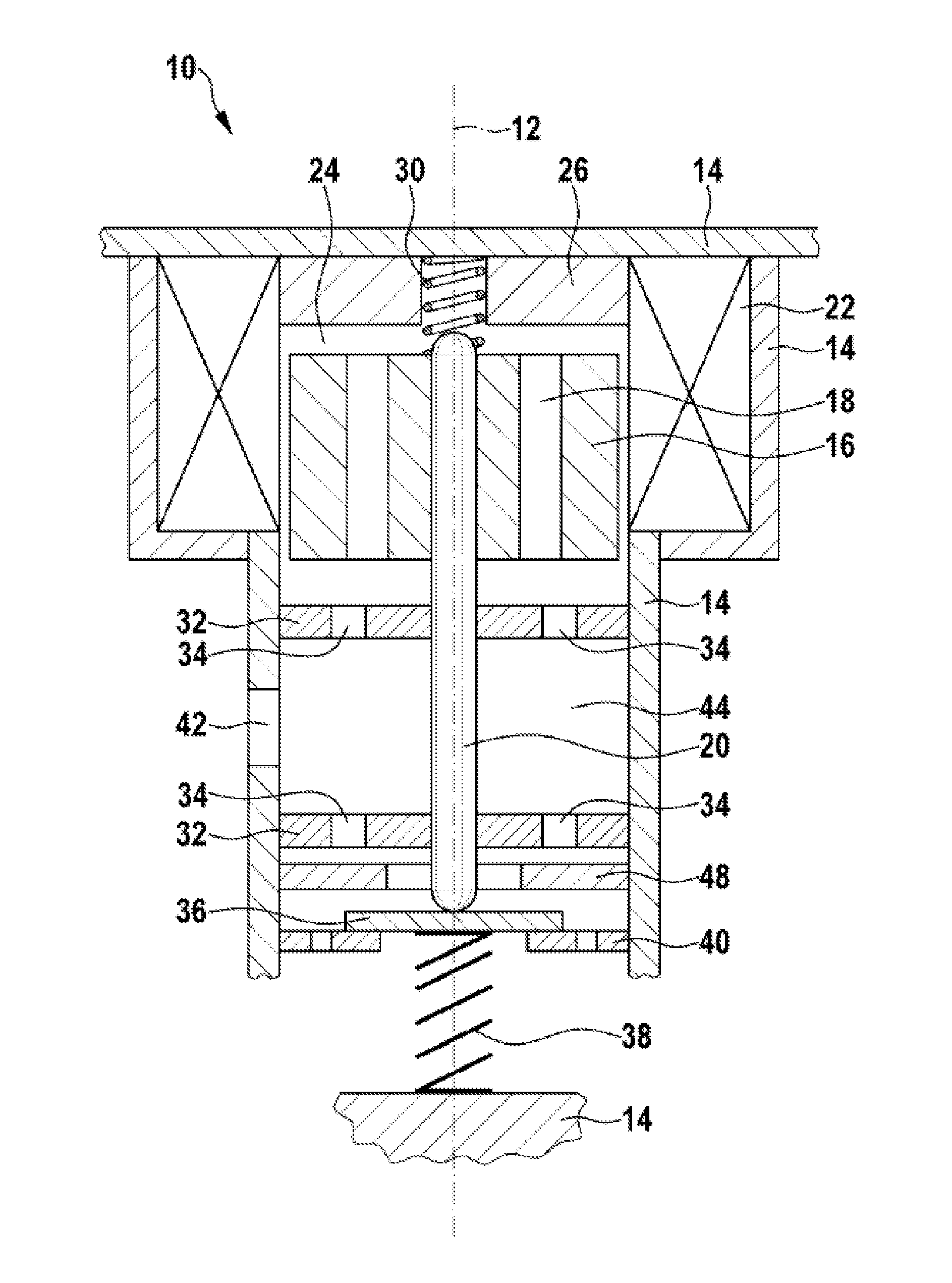
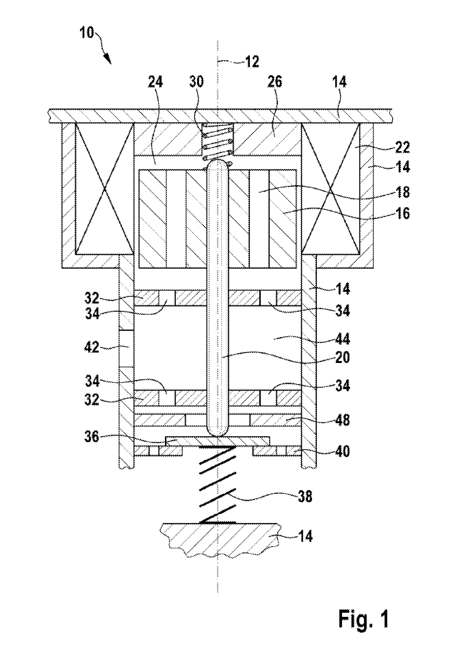
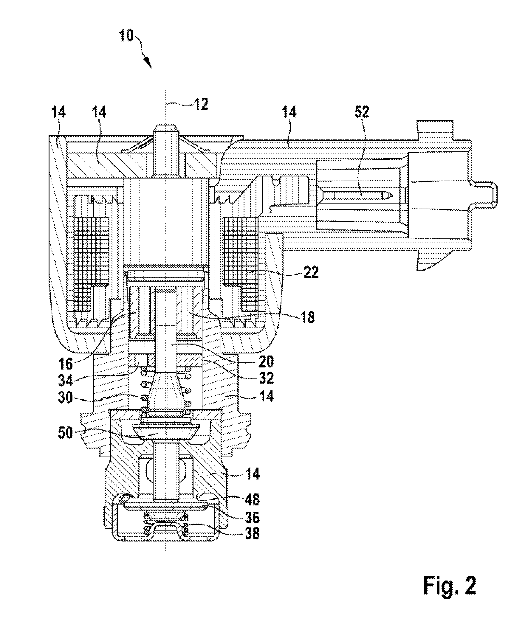
[0024]The same reference numerals are used for functionally equivalent elements and variables in all the Figures even for different embodiments.

[0025]FIG. 1 is a partially sectioned, highly schematic and simplified view of a valve device 10. The valve device is an element of a quantity control valve of an internal combustion engine which is not illustrated and is constructed in a substantially rotationally symmetrical manner about a longitudinal axis 12. The valve device 10 comprises a plurality of different portions of a housing 14, in which elements of the valve device 10 are arranged. An axially movable armature 16 which has axial armature bores 18 is arranged in an upper region of the drawing. The armature 16 is rigidly secured to an end region of a valve element 20, which end region is in the upper portion of the drawing. The valve element 20 is movable and consequently constitutes a movement element 20. An end face of the armature 16, which end face is in the upper portion of ...


PUM


Abstract

A valve device has a movement element, which is cylindrical at least in sections, and a guide element, which has a guide recess for guiding the movement element and is pressed into a valve housing. The guide element comprises a radially inner ring-like section and a radially outer ring-like section. The guide recess is arranged in the inner ring-like section. On its outer circumference, the outer ring-like section has a number of contact sections which are arranged distributed uniformly over the circumference and by means of which the outer ring-like section is pressed into the valve housing. The inner ring-like section is connected to the outer ring-like section via an identical number of connecting sections, which are arranged distributed uniformly in the circumferential direction, wherein, as viewed in the circumferential direction, the connecting sections are offset radially by an angle of 180 DEG/N in relation to the contact sections.

Description

PRIOR ART[0001]The invention relates to a valve device according to the preamble of claim 1.[0002]Magnetic switching valves are known commercially. The lifting movement of an armature is often transmitted therein to a valve member by means of a valve needle which can carry out the actual valve function at a sealing seat. The valve needle is generally guided on portions of a cylindrical outer face (“guiding faces”). Those guiding faces preferably have a hard surface so that the wear remains low over the service-life. This is particularly advantageous if those switching valves switch a brake fluid, a petroleum fuel or a diesel fuel and are flowed through thereby because those media have a low level of lubrication property. Therefore, it is advantageous to bring about the guiding of the needle by means of a separate component which is, for example, hardened. A cost-effective possibility of assembling that guiding component is to press the separate guiding component into a housing porti...

Claims


Application Information

Patent Timeline
IPC IPC(8): F16K31/06
CPCF16K31/06F16K31/0655B60T15/36F02M55/00F02M59/20F16K1/32
Inventor GERUNDT, OLIVERHALLER, JUERGENDEPONTE, RENE
Owner ROBERT BOSCH GMBH
Why Eureka
Try Eureka