Apparatus and method for constructing strength-variable pile in situ by static pressure and drawing
A forming device and cast-in-place technology, which is applied to sheet pile walls, buildings, and foundation structure engineering, can solve problems such as safe construction, achieve the effects of ensuring foundation quality, improving bearing compressive strength, and facilitating grabbing soil
- Summary
- Abstract
- Description
- Claims
- Application Information
AI Technical Summary
Problems solved by technology
Method used
Image
Examples
Embodiment 1
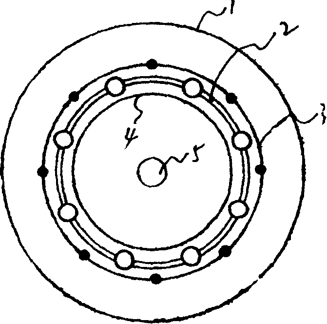
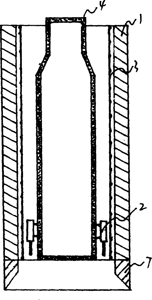
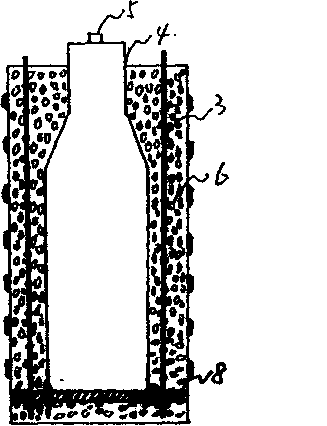
[0021] Embodiment 1: with reference to attached figure 1 and 2 . Static pressure and static pulling cast-in-place variable-strength pile forming device is composed of outer tube 1, concrete vibrator assembly 2, steel cage 3, inner core 4, open pile tip 7 and strong pulling device; the inner core is airbag or tubular hollow Structure or solid core structure, tubular hollow structure is foam tubular hollow structure or wooden tubular hollow structure or tubular resin hollow structure or tubular metal structure, this example adopts built-in airbag, open pile tip 7 is located at the lower end of outer tube 1, open pile Point 7 is made of cast iron or cast steel or reinforced concrete structure and is installed on the lower end of outer tube 1 when the pile hole is statically pressed, and outer tube 1 is made of thick steel plate. The thickness of the steel plate is generally selected between 3-6 cm, and the shape can be Tube shape, rectangle, triangle, T-shape, I-shape, H-shape,...
Embodiment 2
[0022] Embodiment 2: Static pressure and static pulling cast-in-place variable-strength tension pile forming method, ① using static pressure method or vibration method or hammering method to press or vibrate or hammer the outer pipe with the open pile tip into the ground; ② Take out the soil in the outer tube; ③Inject a certain thickness of concrete into the inner cavity of the open pile tip; ④Fix the steel bar at the bottom of the reinforcement cage with the strong tension positioning steel plate and put it into the cavity of the open pile tip, and then inject a certain thickness of concrete ; ⑤ Put the inner core into the steel cage; ⑥ Put the concrete vibrator assembly between the inner core and the steel cage, and then gradually inject concrete into the space formed by the inner core and the outer tube. When the concrete is injected into a certain height, Start the concrete vibrator assembly to vibrate until the set time, so that the air bubbles in the concrete are discharg...
Embodiment 3
[0023] Embodiment 3: On the basis of Embodiment 1 and 2, the formed pipe pile can be a tongue-and-groove concrete pipe pile, as attached Figure 4 ; It can also be a triangular pipe pile, as attached Figure 5 ; It can also be a T-shaped pipe pile, such as attached Figure 6 ; It can also be an I-shaped pipe pile, such as attached Figure 7 ; It can also be a circular tubular pile, such as attached Figure 8 . All of the above-mentioned concrete pipe piles are provided with reinforcement cages 3 .
PUM
 Abstract
Description
Claims
Application Information
 - R&D
- Intellectual Property
- Life Sciences
- Materials
- Tech Scout
- Unparalleled Data Quality
- Higher Quality Content
- 60% Fewer Hallucinations
Browse by: Latest US Patents, China's latest patents, Technical Efficacy Thesaurus, Application Domain, Technology Topic, Popular Technical Reports.
© 2025 PatSnap. All rights reserved.Legal|Privacy policy|Modern Slavery Act Transparency Statement|Sitemap|About US| Contact US: help@patsnap.com


