
Low-stress fixture for cutting test on metal test piece

A cutting test and metal test piece technology, applied in metal processing machinery parts, workpiece clamping devices, metal processing equipment, etc. Small deformation and the effect of reducing residual stress

Inactive Publication Date: 2017-07-04
CHANGHE AIRCRAFT INDUSTRIES CORPORATION +1
View PDF6 Cites 0 Cited by
  • Summary
  • Abstract
  • Description
  • Claims
  • Application Information

AI Technical Summary

Problems solved by technology

[0003] In the actual test, in order to save materials and reduce costs, the size of the metal test piece is generally small. At this time, the clamping force generated when clamping the metal test piece is relatively large, which will cause the parts to be clamped before machining. A slight deformation is generated. When the specimen is processed, the release of this part of the clamping force will affect the deformation of the specimen, which will eventually cause the measured value of the residual stress on the machined surface of the part to be different from the actual value.

Method used


Image

  • Low-stress fixture for cutting test on metal test piece
  • Low-stress fixture for cutting test on metal test piece
  • Low-stress fixture for cutting test on metal test piece

Examples

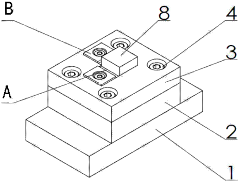
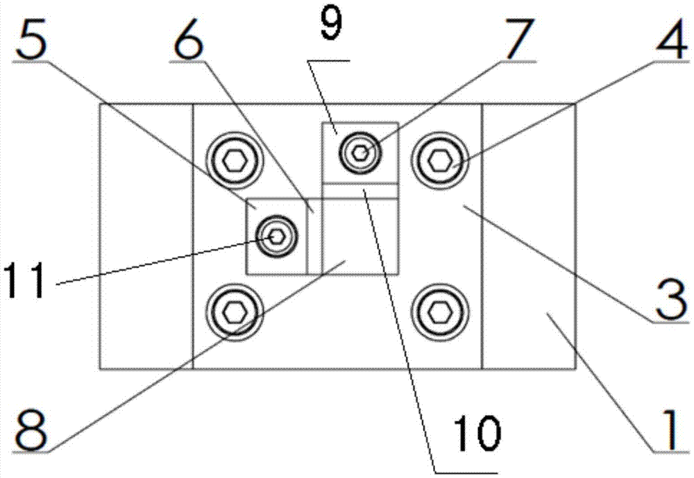
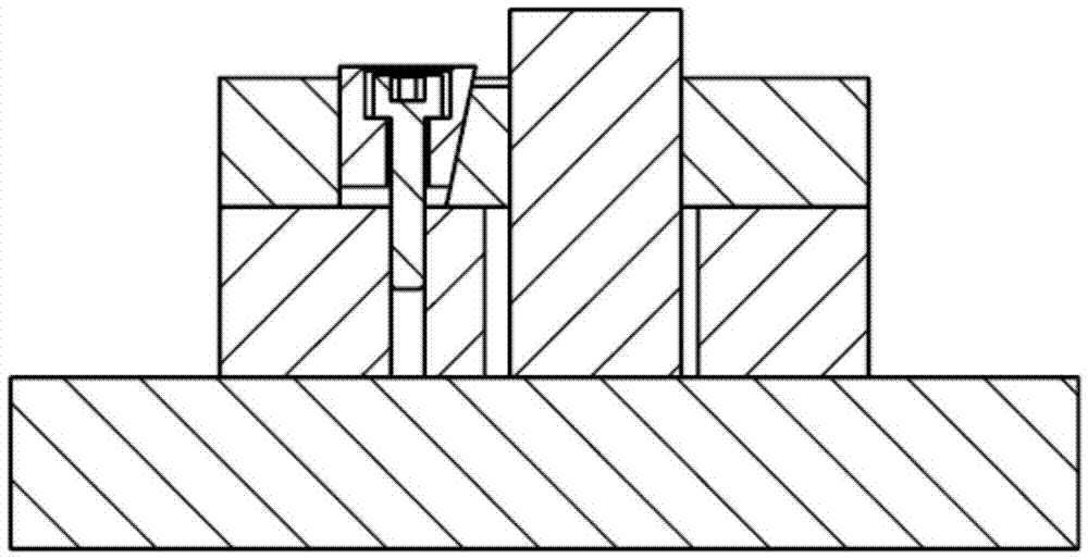

Embodiment Construction

[0023] The specific embodiment of the present invention will be further described in conjunction with accompanying drawing:

[0024] A low-stress fixture for cutting tests on metal specimens, characterized in that,

[0025] Including the lower base 1, the middle base 2, the upper base 3, the upper base 3 has an L-shaped through hole, the middle base 2 has a through square mounting hole, the square test piece 8 passes through the L-shaped through hole and the square mounting hole in turn, The bottom surface of the square test piece 8 is pressed on the upper surface of the lower base 1,

[0026] It also includes a first clamping block A and a second clamping block B, the first clamping block A and the second clamping block B are vertically arranged in the L-shaped through hole, and the square test piece 8 passes through the first reference plane perpendicular to each other Positioning with the second reference plane, the first clamping block A presses against the opposite surfa...


PUM


Abstract

The invention provides a low-stress fixture for a cutting test on a metal test piece. The low-stress fixture is characterized by comprising a lower base [1], a middle base [2] and an upper base [3], wherein an L-shaped through hole is formed in the upper base [3]; a square penetrating installation hole is formed in the middle base [2]; a square test piece [8] sequentially penetrates through the L-shaped through hole and the square installation hole; and the bottom surface of the square test piece [8] is pressed on the upper surface of the lower base [1]. The low-stress fixture further comprises a first jacking block [A] and a second jacking block [B], wherein the first jacking block [A] and the second jacking block [B] are vertically arranged in the L-shaped through hole; the square test piece [8] is located through a first reference surface and a second reference surface which are mutually vertical; the first jacking block [A] tightly jacks the opposite surface of the first reference surface; the second jacking block [B] tightly jacks the opposite surface of the second reference surface; and the lower base [1], the middle base [2] and the upper base [3] are fixed into one piece through screws [4].

Description

technical field [0001] The invention relates to a low-stress fixture used for cutting tests of metal test pieces, and is especially suitable for measuring and researching the residual stress on the cutting surface of standard metal test pieces. The fixture can greatly weaken the influence of the clamping force of the test piece on the residual stress of the machined surface of the test piece, and has high reliability and safety. Background technique [0002] Mechanical or mechanical parts build up internal residual stresses during the manufacturing process. Residual stress is the cause of process defects such as deformation and cracking during component manufacturing, and the residual stress inside the component after processing will affect various mechanical properties of materials such as corrosion and fatigue strength. Therefore, it is of great significance to accurately measure the residual stress on the machined surface of parts to improve the corrosion resistance and ...

Claims


Application Information

Patent Timeline
Patent Type & Authority Applications(China)
IPC IPC(8): B23Q3/06B25B11/00
CPCB23Q3/06B25B11/00
Inventor 卢廷钧陈志同赵汉卿吴小文屈新河陈其南蒋理科王勇
Owner CHANGHE AIRCRAFT INDUSTRIES CORPORATION
Learn More