Apparatus and method for controlled fluid cooling during laser based dental treatments

a laser-based dental treatment and fluid cooling technology, applied in dental surgery, tooth rinsing, medical science, etc., can solve the problems of reducing affecting the efficiency of dental tissue cutting, and fracturing the hard tissue/enamel, so as to facilitate effective dental treatment and reduce the risk of enamel melting by laser beams. , the effect of significantly affecting the efficiency of cutting dental tissu

Active Publication Date: 2013-12-05
CONVERGENT DENTAL INC
View PDF3 Cites 2 Cited by
  • Summary
  • Abstract
  • Description
  • Claims
  • Application Information

AI Technical Summary

Benefits of technology

[0011]In various embodiments, a system and a method in accordance with the present invention facilitates effective dental treatment in which the risk of melting of the enamel by a laser beam is mitigated or eliminated without significantly impacting the efficiency of cutting the dental tissue. This is achieved, in part, by regulating the flow of a coolant fluid such that an amount of fluid present in the treatment area is adequate to minimize the risk of melting of the enamel, but is not so excessive as to interfere with the laser beam by absorbing a significant portion of the laser energy. Specifically, because molten enamel can cover hydroxyapatite, and thus substantially prevent absorption of the laser energy thereby, the system and method ensure that an amount of water / coolant that is sufficient to inhibit or minimize melting of the enamel is present in the treatment area. The amount of water / coolant is minimized, however, so that the portion of radiation absorbed into the water / coolant is minimized and absorption of the laser energy by the hydroxyapatite / enamel to be removed is maximized or maintained near the peak absorption. As a result, the portion of the generated laser energy that is utilized for ablation can be maximized so that the cost and / or duration of the mid to far-infrared laser based treatment is minimized, while preventing melting of the enamel. As part of regulating the flow of the coolant fluid, both the location and amount of cooling fluid may be controlled. Various embodiments may also employ computer controlled laser beam delivery.

Problems solved by technology

Typically, the applied laser energy is absorbed in water in tooth enamel (about 4% by volume), causing the water to vaporize, and the resulting steam causing to fracture the hard tissue / enamel and thus removing a portion of the enamel from the tooth.
Because the laser wavelength is chosen such that a significant portion of the laser energy is strongly absorbed by water, a common problem with such systems is that the cutting operation is slow, due to the low percentage of water in the enamel.
In fact, this method of removing dental hard tissue is often considerably slower than using dental drills and many dental procedures are completed in less time by an operator / dentist using a conventional drill than by using a laser that operates by absorption of laser energy in water.
For this reason may practitioners choose not to use laser based systems for dental treatment, and as such the benefits that laser based treatment can offer are not widely available at present.
When the laser is used to fracture the tooth structure by water vaporization, water provided by the system to cool the treatment area can interfere with the laser beam without a significant reduction in material removal rates.
In some systems, the coolant system is intentionally configured such that the coolant interferes with the laser beam to impart disruptive forces on dental hard tissue.
Some systems that deliver coolant between laser pulses do not provide forced convective cooling from the surface of the dental region being treated at or nearly at the time the surface is being heated.
This can cause the treated surface to experience thermal cycles, heating during laser pulses and cooling in between such pulses.
In such systems, providing unregulated quantities of water or other coolants is often not a beneficial solution to solve the problem of the melting of the enamel.
Therefore, an excess amount of water can interfere with the cutting operation of the laser beam.
In addition, though the melting of the enamel can decrease the efficiency of cutting in general, this problem can be significant when mid to far infrared lasers are used.

Method used


Image

  • Apparatus and method for controlled fluid cooling during laser based dental treatments
  • Apparatus and method for controlled fluid cooling during laser based dental treatments
  • Apparatus and method for controlled fluid cooling during laser based dental treatments

Examples


Embodiment Construction

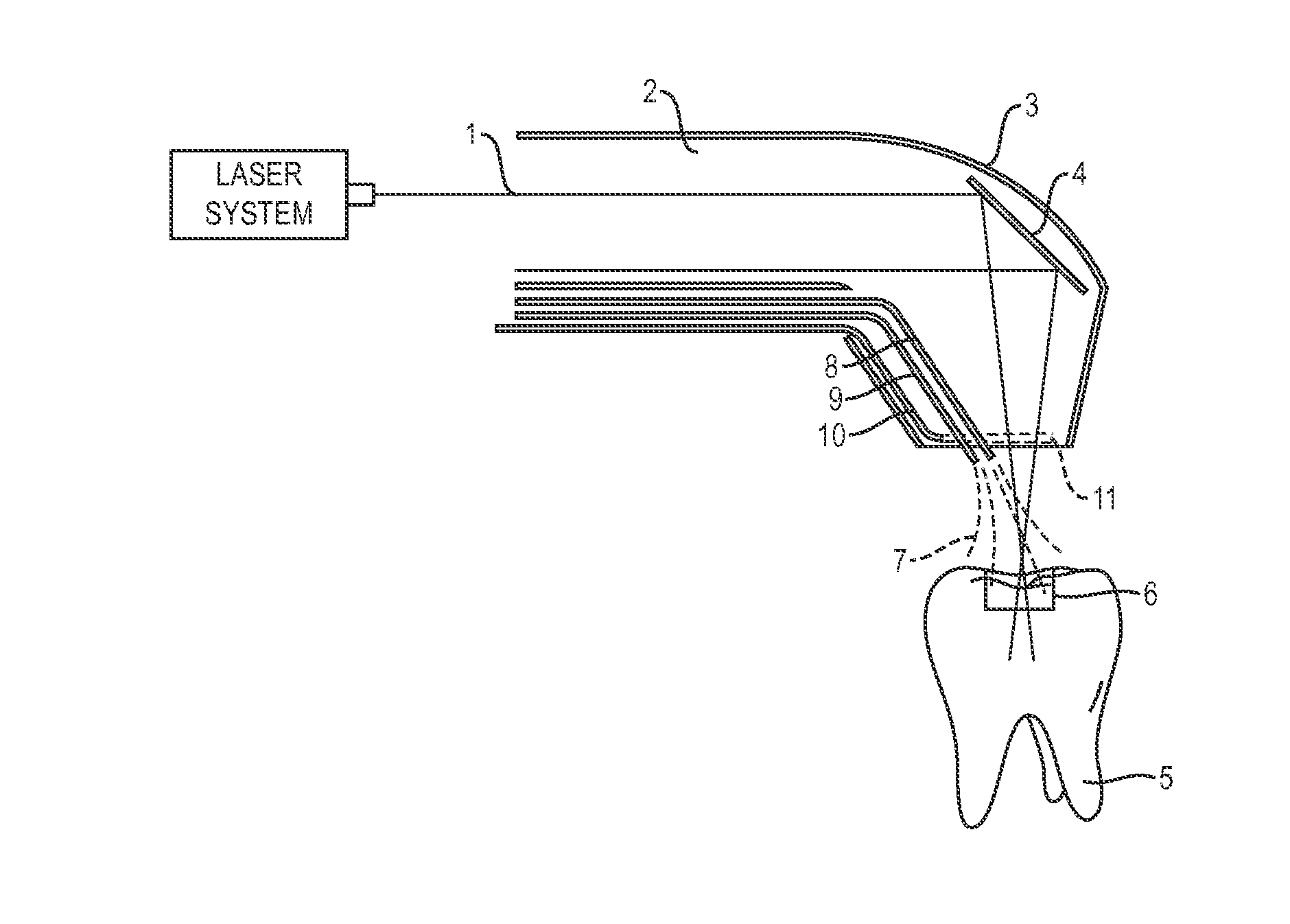
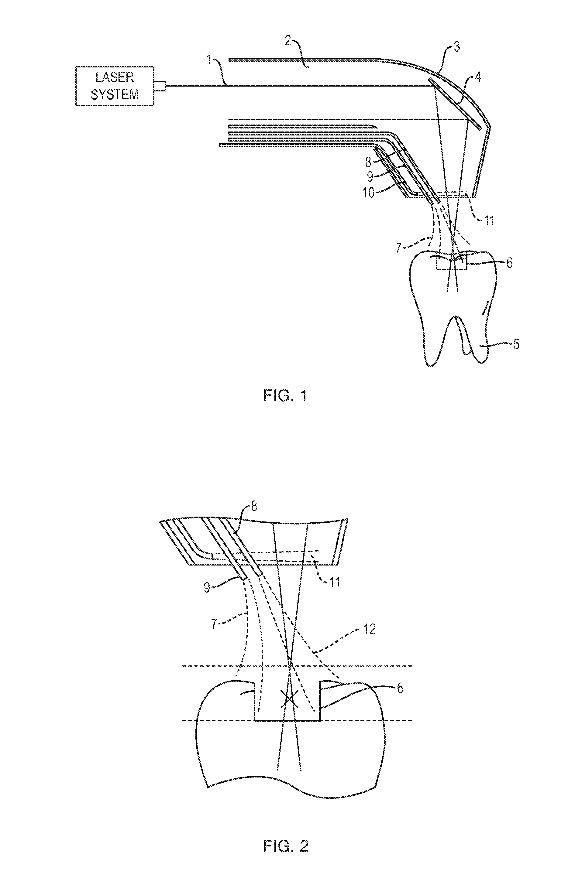
[0034]A process is disclosed that combines a laser based dental treatment system with a controlled delivery of cooling fluid. The laser based system may be computer controlled and the coolant fluid delivery system may include an air curtain to limit the amount of cooling fluid that could interfere with the laser beam.

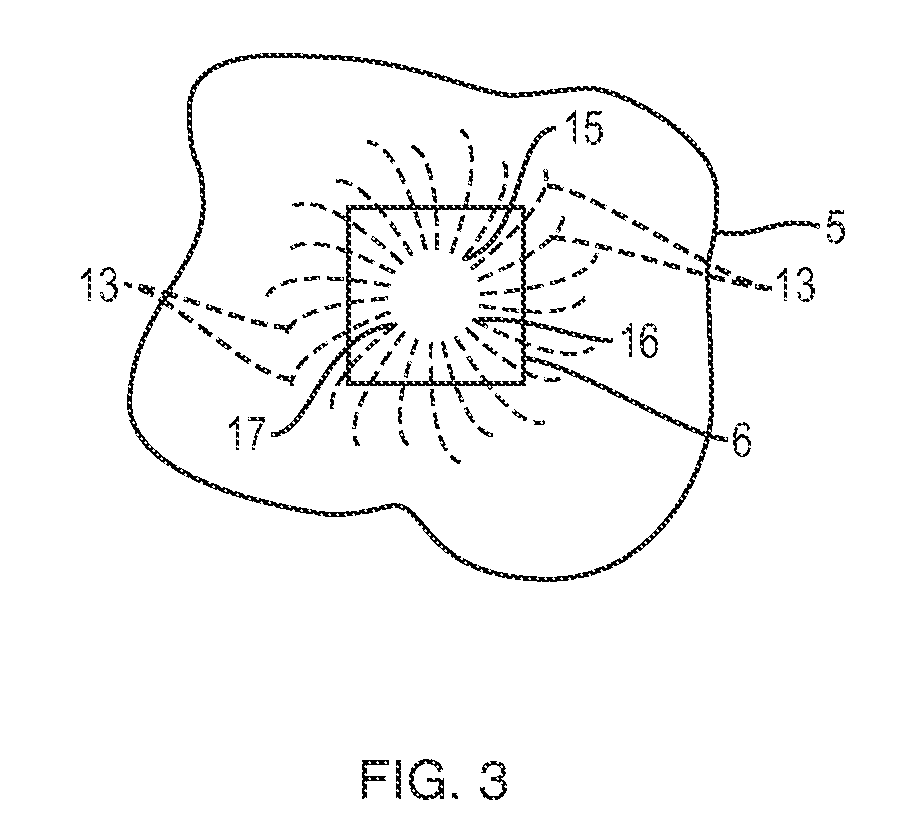
[0035]FIG. 1 depicts one embodiment in which a laser beam 1 emerges from a hand piece 2, which is a part of the laser treatment / cutting system 3. The laser beam can be computer controlled, and is reflected off a mirror 4 to perform the cutting operation on the tooth 5 or other tissue The user can select the geometry of the cut 6 and the depth of the cut 6. Cooling fluid 7 is directed to the tooth 5 via nozzles 8 and 9. This fluid provides both the critical cooling needed to fully control the cutting but also helps to remove the cut material from the tooth 5. A separate nozzle assembly 10 supplies an air curtain 11 that may keep the cooling fluid from splashing back into...


PUM


Abstract

A system for dental tissue treatment includes a system for directing a laser beam to an area of dental tissue to be treated, and a fluid-delivery system for directing and controlling a flow of a fluid. The fluid is directed to at least a portion of the area to be treated and the fluid flow is controlled to substantially prevent both a change in laser energy absorption by the dental tissue and attenuation of treatment efficiency due to fluid interference with the laser beam. The fluid present in at least a portion of the area to be treated may prevent or reduce the likelihood of melting of enamel in that area.

Description

CROSS REFERENCE TO RELATED APPLICATIONS[0001]This application is related to and claims the benefit of priority to U.S. Provisional Patent Application Ser. No. 61 / 646,579 filed on May 14, 2012, the entirety of which is hereby incorporated by reference.FIELD OF THE INVENTION[0002]This invention relates to coolant systems and in particular to coolant systems for laser-based dental treatment.BACKGROUND[0003]Some dental treatment systems use lasers, e.g., for cutting tooth enamel. It may be beneficial to replace drills conventionally used in dental treatment with laser-based systems, in part because lasers can provide for better control of the process of cutting and removing material from a tissue to be treated, such as a tooth. Also, laser-based systems are typically less noisy and may produce less vibrations than a conventional drill. Lasers have also been found to be useful in the removal of dental material with less amount of local anesthetic than that required when the procedure is ...

Claims


Application Information

Patent Timeline
Patent Type & Authority Applications(United States)
IPC IPC(8): A61C1/00A61C19/06
CPCA61C1/0069A61C1/0046A61C19/063A61C1/0061A61C1/052A61C1/087A61C17/0217
Inventor MONTY, NATHAN P.DRESSER, CHARLES H.
Owner CONVERGENT DENTAL INC
Why Eureka
Try Eureka