

Rotational shear valve
a technology of rotating shear valve and tubular member, which is applied in the direction of valve housing, sealing/packing, and well accessories, to achieve the effect of reducing the likelihood of damage to the sealing surface, removing or cleaning the coil tubing, and reducing the likelihood of damag
- Summary
- Abstract
- Description
- Claims
- Application Information
AI Technical Summary
Benefits of technology
Problems solved by technology
Method used
Image

Examples
Embodiment Construction
[0022]The present invention will now be described more fully hereinafter with reference to the accompanying drawings which illustrate embodiments of the invention. This invention may, however, be embodied in many different forms and should not be construed as limited to the illustrated embodiments set forth herein. Rather, these embodiments are provided so that this disclosure will be thorough and complete, and will fully convey the scope of the invention to those skilled in the art. Like numbers refer to like elements throughout, and the prime notation, if used, indicates similar elements in alternative embodiments.
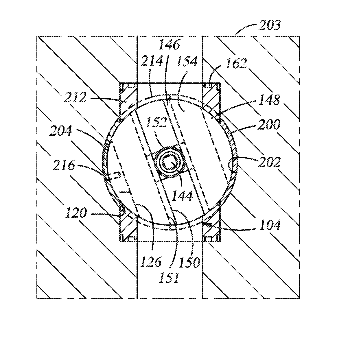
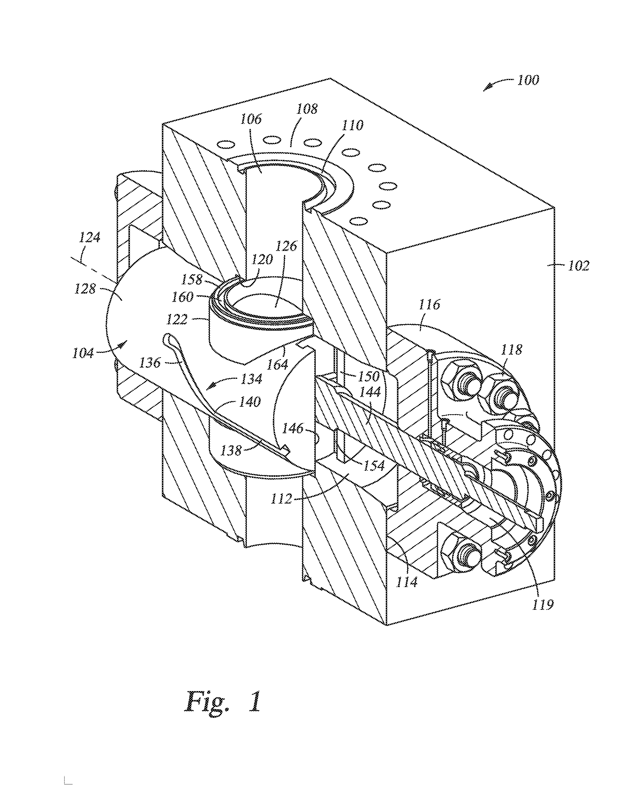
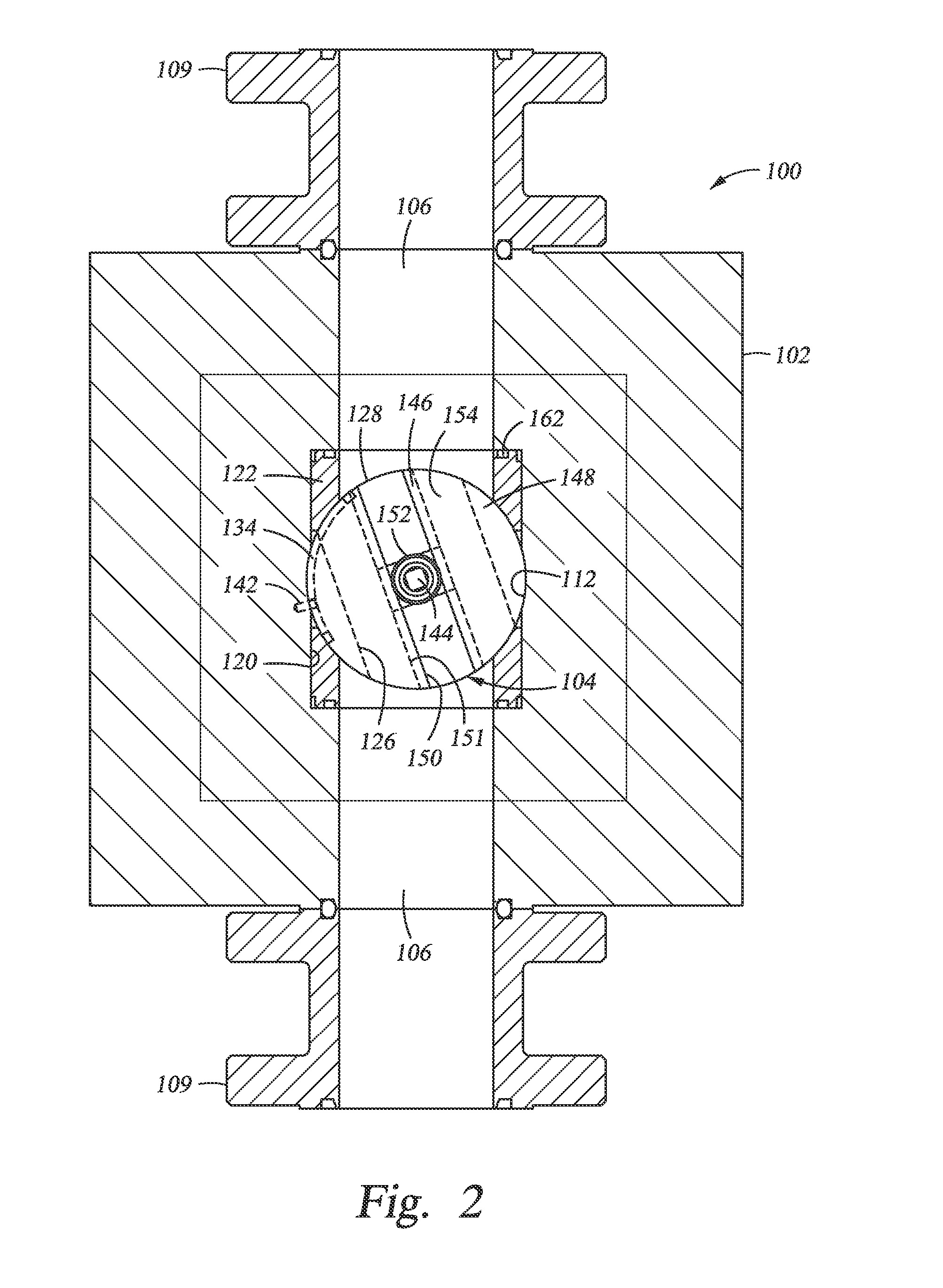
[0023]Referring to FIG. 1, a valve assembly 100 is a valve assembly that can be used to selectively control the flow of fluids through a passage. Valve assembly 100 can be used, for example, to control flow through a tubular member such as a wellhead housing or a riser that is connected to a wellbore (not shown) of a mineral recovery well. Embodiments of valve assembly 1...
PUM
 Abstract
Description
Claims
Application Information