Device for braking and rotating an aircraft wheel

a technology for aircraft wheels and rotors, applied in the direction of aircraft braking arrangements, braking systems, transportation and packaging, etc., can solve the problems of loss of braking function, large size and weight of motors,

Inactive Publication Date: 2013-12-12
SAFRAN LANDING SYSTEMS
View PDF2 Cites 22 Cited by
  • Summary
  • Abstract
  • Description
  • Claims
  • Application Information

AI Technical Summary

Problems solved by technology

Nevertheless, it is necessary for the motor to be dimensioned to be capable of withstanding the maximum braking torque, which may lead to using a motor of large size and weight.
In addition, in the event of the motor failing, the braking function is lost, since it is no longer possible to block the ring.

Method used


Image

  • Device for braking and rotating an aircraft wheel
  • Device for braking and rotating an aircraft wheel

Examples


Embodiment Construction

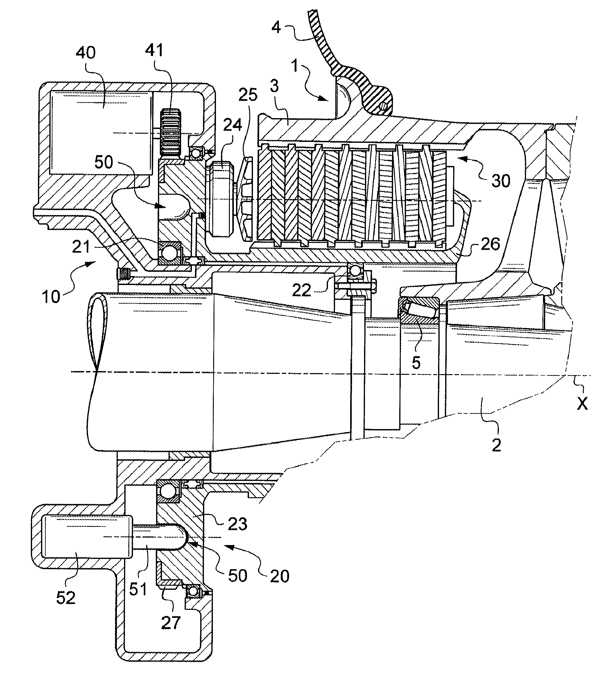
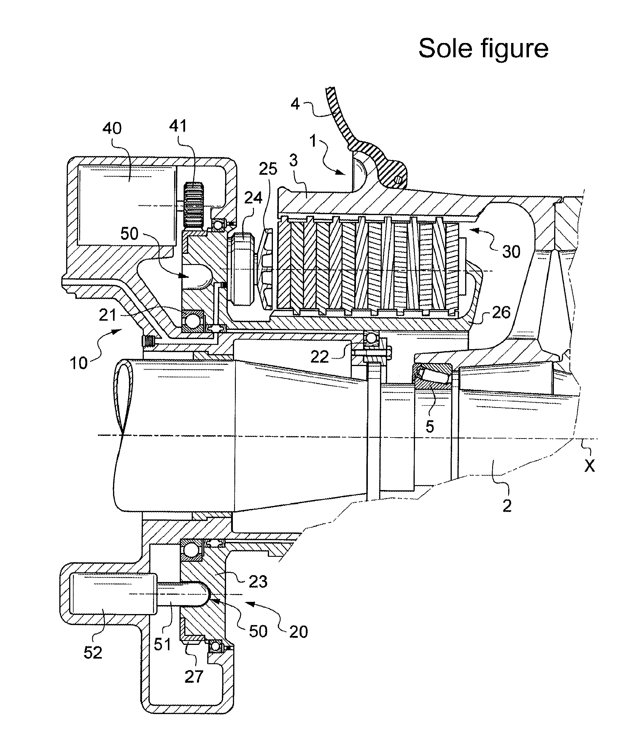
[0014]The invention is described herein with reference to a wheel 1 mounted to rotate on a landing gear axle 2. The wheel 1 comprises a rim 3 carrying a tire 4 and mounted on the axle by means of rolling bearings 5 (only one of which is shown in the FIGURE) so as to rotate about an axis of rotation X.

[0015]The device of the invention comprises a base 10 that is mounted around the axle 2 and that is prevented from rotating by stop means (not shown). For example, the base 10 may be fastened to a collar of the axle 2.

[0016]A rotary portion 20 is mounted on the base 10 to rotate about it via rolling bearings 21 and 22. The rotary portion 20 comprises a ring 23 carrying braking actuators 24, constituted in this example by hydraulic actuators, each having an axially movable piston 25. The rotary portion 20 also has a torsion tube 26 that extends inside the rim 3. Between the rim 3 and the torsion tube 26 there extends a stack of disks 30 comprising in alternation first disks that are cons...


PUM


Abstract

The invention relates to a device for braking and driving rotation of a wheel (1) mounted to rotate on an aircraft landing gear axle, the device comprising: a torsion tube (26) adapted to be mounted to rotate on the axle that carries the wheel; a stack of disks (30) including first disks having means for constraining them in rotation with the wheel and second disks arranged in alternation with the first disks and including means for constraining them in rotation with the torsion tube; a ring (23) carrying braking actuators (24) that are adapted to act selectively to press the disks against one another, the ring being constrained in rotation with the torsion tube in order to form a rotary portion (20) of the device; a rotary drive member (40) for driving rotation of the rotary portion (20); and finally blocking means (51, 52) for selectively blocking rotation of the rotary portion, which means are independent of the rotary drive member.

Description

[0001]The invention relates to a device for braking and driving rotation of an aircraft wheel.TECHNOLOGICAL BACKGROUND OF THE INVENTION[0002]Document U.S. Pat. No. 3,977,631 describes landing gear including at least one axle rotatably carrying a wheel that is fitted with a brake. The brake comprises a stack of disks, some of which constrained in rotation with the wheel and others of which, arranged in alternation with the first disks, are constrained in rotation with a torsion tube. The torsion tube is itself mounted to rotate on the axle and is constrained in rotation with a ring that carries braking actuators.[0003]The ring is selectively driven in rotation or blocked by means of an electric motor. Thus, by actuating the braking actuators so that the disks are pressed against one another, while also actuating the electric motor, the ring is secured to the wheel and the electric motor drives the wheel in rotation, thereby enabling the aircraft to be moved without using its engines....

Claims


Application Information

Patent Timeline
Patent Type & Authority Applications(United States)
IPC IPC(8): B64C25/40
CPCB64C25/405B60T13/741B64C25/36B64C25/44F16D55/36Y02T50/80
Inventor YIU, JEAN-MARC
Owner SAFRAN LANDING SYSTEMS
Why Eureka
Try Eureka