Nanocarbide precipitation strengthened ultrahigh-strength, corrosion resistant, structural steels

a technology of nanocarbide precipitation and structural steel, which is applied in the field of nickel, chromium stainless martensitic steel alloy, can solve the problems of poor general corrosion resistance of ultrahigh-strength steels, and inability to meet the requirements of use, etc., and achieves the effect of convenient work

Inactive Publication Date: 2007-01-09
QUESTEK INNOVATIONS LLC
View PDF8 Cites 48 Cited by
  • Summary
  • Abstract
  • Description
  • Claims
  • Application Information

AI Technical Summary

Benefits of technology

[0017]Yet another object of the invention is to provide ultrahigh-strength, corrosion resistant, structural steel alloys which ma

Problems solved by technology

Main structural components in aerospace and other high-performance structures are almost exclusively made of ultrahigh-strength steels because the weight, size and, in some cases, cost penalties associated with use of other materials is prohibitive.
However, ultrahigh-strength steels with a tensile strength in the range of at least 240 ksi to 300 ksi have poor general corrosion resistance and are susceptible to hydrogen and environmental embrittlement.
These coatings have disadvantages from a cost, manufacturing, enviro

Method used


Image

  • Nanocarbide precipitation strengthened ultrahigh-strength, corrosion resistant, structural steels
  • Nanocarbide precipitation strengthened ultrahigh-strength, corrosion resistant, structural steels
  • Nanocarbide precipitation strengthened ultrahigh-strength, corrosion resistant, structural steels

Examples


experimental results and examples

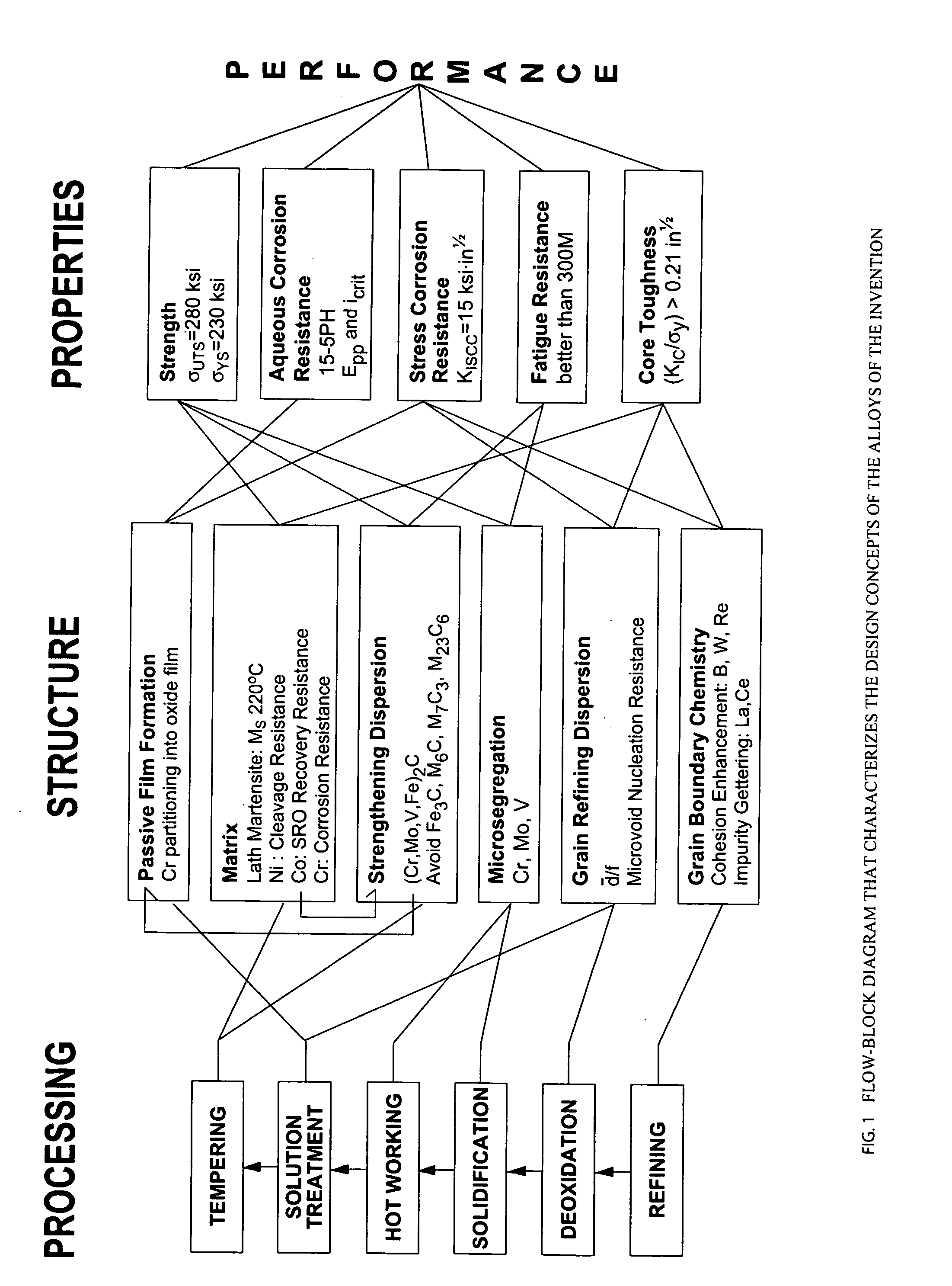
[0074]A series of prototype alloys were prepared. The melt practice for the refining process was selected to be a double vacuum melt with La and Ce impurity gettering additions. Substitutional grain boundary cohesion enhancers such as W and Re were not considered in the making of the first prototype, but an addition of twenty parts per million B was included for this purpose. For the deoxidation process, Ti was added as a deoxidation agent, promoting TiC particles to pin the grain boundaries and reduce grain growth during solution treatment prior to tempering.

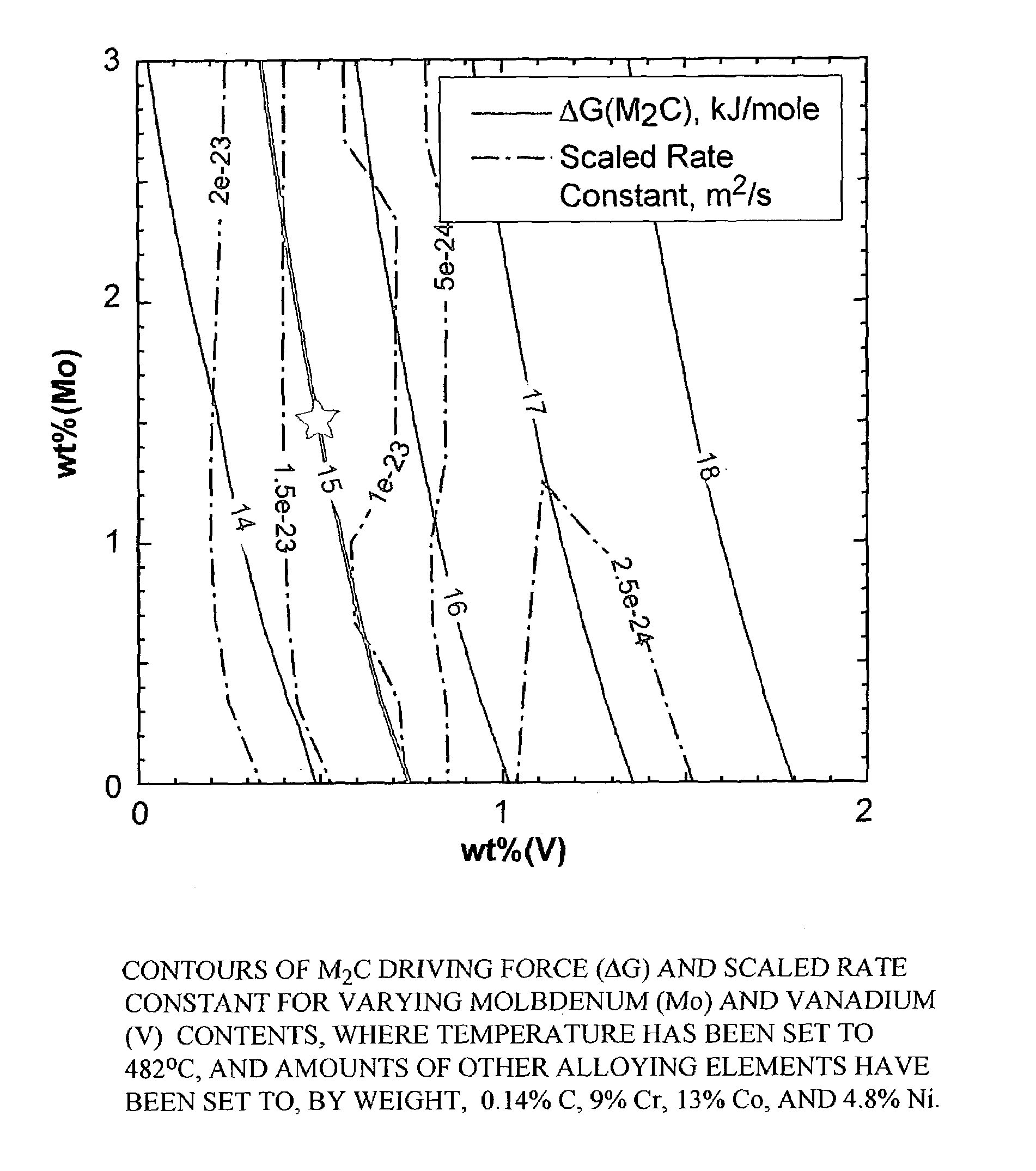
[0075]The major alloying elements in the first prototype are C, Mo, and V (M2C carbide formers), Cr (M2C carbide former and oxide passive film former), and Co and Ni (for various required matrix properties). The exact alloy composition and material processing parameters were determined by an overall design synthesis considering the linkages and a suite of computational models described elsewhere [Olson, G. B, “Computational Des...

example 1

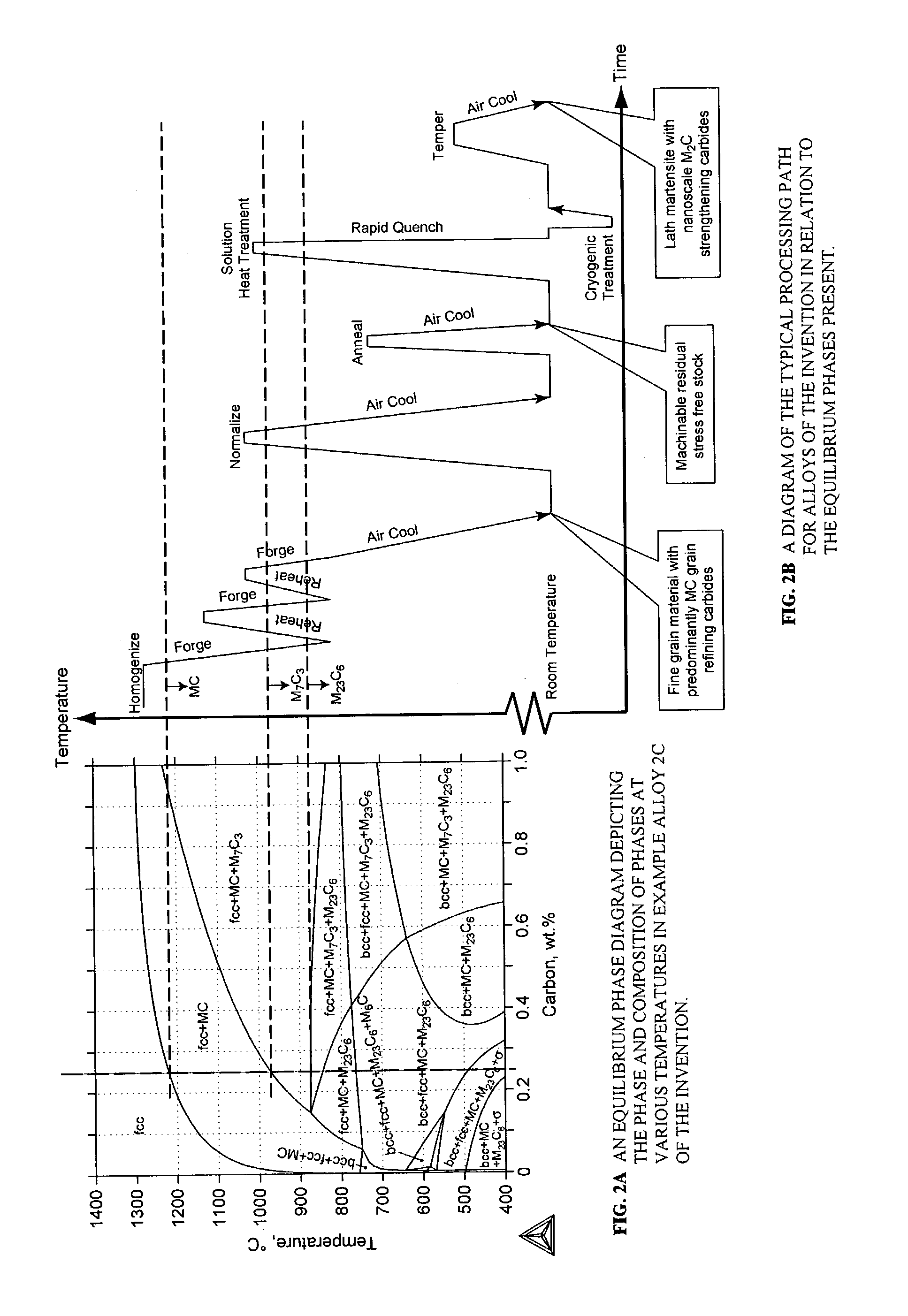
[0086]Alloy 1 in TABLE 1 was vacuum induction melted (VIM) to a six inch diameter electrode which was subsequently vacuum arc remelted (VAR) to a eight inch diameter ingot. The material was homogenized for seventy-two hours at 1200° C., forged and annealed according to the preferred processing techniques described above and depicted in FIGS. 2A and 2B. Dilatometer samples were machined and the Ms temperature was measured as 175° C. by quenching dilatometry and 1% transformation fraction.

[0087]Test samples were machined, solution heat treated at 1025° C. for one hour, oil quenched, immersed in liquid nitrogen for one hour, warmed to room temperature and tempered at 482° C. for eight hours. The measured properties are listed in TABLE 2 below.

[0088]

TABLE 2Various measured properties for Alloy 1PropertyValueYield Strength205ksiUltimate Tensile Strength245ksiElongation10%Reduction of Area48%Hardness51HRC

example 2

[0089]Alloy 2A in TABLE 1 was vacuum induction melted (VIM) to a six inch diameter electrode which was subsequently vacuum arc remelted (VAR) to a eight inch diameter ingot. The ingot was homogenized for twelve hours at 1190° C., forged and rolled to 1.500 inch square bar starting at 1120° C., and annealed according to the preferred processing techniques described above and depicted in FIGS. 2A and 2B. Dilatometer samples were machined and the Ms temperature was measured as 265° C. by quenching dilatometry and 1% transformation fraction.

[0090]Test samples were machined from the square bar, solution heat treated at 1050° C. for one hour, oil quenched, immersed in liquid nitrogen for one hour, warmed to room temperature, tempered at 500° C. for five hours, air cooled, immersed in liquid nitrogen for one hour, warmed to room temperature and tempered at 500° C. for five and one-half hours. The measured properties are listed in TABLE 3 below. The reference to the corrosion rate of 15-5PH...


PUM

PropertyMeasurementUnit
Fractionaaaaaaaaaa
Fractionaaaaaaaaaa
Fractionaaaaaaaaaa

Abstract

A nanocarbide precipitation strengthened ultrahigh-strength, corrosion resistant, structural steel possesses a combination of strength and corrosion resistance comprising in combination, by weight, about: 0.1 to 0.3% carbon (C), 8 to 17% cobalt (Co), 0 to 10% nickel (Ni), 6 to 12% chromium (Cr), less than 1% silicon (Si), less than 0.5% manganese (Mn), and less than 0.15% copper (Cu), with additives selected from the group comprising about: less than 3% molybdenum (Mo), less than 0.3% niobium (Nb), less than 0.8% vanadium (V), less than 0.2% tantalum (Ta), less than 3% tungsten (W), and combinations thereof, with additional additives selected from the group comprising about: less than 0.2% titanium (Ti), less than 0.2% lanthanum (La) or other rare earth elements, less than 0.15% zirconium (Zr), less than 0.005% boron (B), and combinations thereof, impurities of less than about: 0.02% sulfur (S), 0.012% phosphorus (P), 0.015% oxygen (O) and 0.015% nitrogen (N), the remainder substantially iron (Fe), incidental elements and other impurities. The alloy is strengthened by nanometer scale M2C carbides within a fine lath martensite matrix from which enhanced chemical partitioning of Cr to the surface provides a stable oxide passivating film for corrosion resistance. The alloy, with a UTS in excess of 280 ksi, is useful for applications such as aircraft landing gear, machinery and tools used in hostile environments, and other applications wherein ultrahigh-strength, corrosion resistant, structural steel alloys are desired.

Description

CROSS REFERENCE TO RELATED APPLICATIONS[0001]This is a continuation-in-part utility application based upon U.S. Ser. No. 10 / 071,688, filed Feb. 8, 2002, which is based on the following provisional applications which are incorporated herewith by reference and for which priority is claimed: U.S. Ser. No. 60 / 267,627, filed Feb. 9, 2001, entitled, “Nano-Precipitation Strengthened Ultra-High Strength Corrosion Resistant Structural Steels” and U.S. Ser. No. 60 / 323,996 filed Sep. 21, 2001 entitled, “Nano-Precipitation Strengthened Ultra-High Strength Corrosion Resistant Structural Steels”.BACKGROUND OF THE INVENTION[0002]In a principal aspect, the present invention relates to cobalt, nickel, chromium stainless martensitic steel alloys having ultrahigh strength and corrosion resistance characterized by nanoscale sized carbide precipitates, in particular, M2C precipitates.[0003]Main structural components in aerospace and other high-performance structures are almost exclusively made of ultrah...

Claims


Application Information

Patent Timeline
IPC IPC(8): C22C38/52C21D9/00C21D8/00C22C38/00C22C38/44C22C38/46C22C38/50C22C38/54
CPCC21D6/02C21D6/04C21D8/005C22C38/52C22C38/44C22C38/46C22C38/50C22C33/0285B22F2998/00C21D2211/003C21D2211/004
Inventor KUEHMANN, CHARLES J.OLSON, GREGORY B.JOU, HERNG-JENG
Owner QUESTEK INNOVATIONS LLC
Why Eureka
Try Eureka