Aircraft landing gear compression rate monitor and method to increase aircraft landing weight limitation

Active Publication Date: 2012-05-15
NANCE C KIRK
View PDF23 Cites 47 Cited by
  • Summary
  • Abstract
  • Description
  • Claims
  • Application Information

AI Technical Summary

Benefits of technology

[0063]One object of the present invention is to allow a

Problems solved by technology

As the landing gear comes into initial contact with the ground, the strut begins to compress, thereby increasing the pressure within the shock absorber.
Aircraft have limitations regarding the maximum allowable force the aircraft landing gear and other supporting structures of the aircraft can safely absorb when the aircraft lands.
This causes an overweight landing event.
As a result, an aircraft may take off with un-used capacity, because its take-off weight is less than the take-off weight limit.
The weight carrying ability of the aircraft is thus limited, not by the maximum take-off weight limitation, but by the landing weight limitation.
Though current regulations for aircraft design criteria acknowledge aircraft structural integrity to allow the aircraft to land at a weight greater than the originally certified MLW for that aircraft, with there being no active and operational system to accurately measure the VVG of those higher landing weight aircraft, there have been no justifications for the aviation Regulatory Authorities to allow for planned or scheduled landing events at the higher weights.
When aircra

Method used


Image

  • Aircraft landing gear compression rate monitor and method to increase aircraft landing weight limitation
  • Aircraft landing gear compression rate monitor and method to increase aircraft landing weight limitation
  • Aircraft landing gear compression rate monitor and method to increase aircraft landing weight limitation

Examples


Embodiment Construction

[0107]In the description herein, the disclosures and all other information of my earlier U.S. Pat. Nos. 7,193,530; 7,274,309 and 7,274,310 are incorporated by reference.

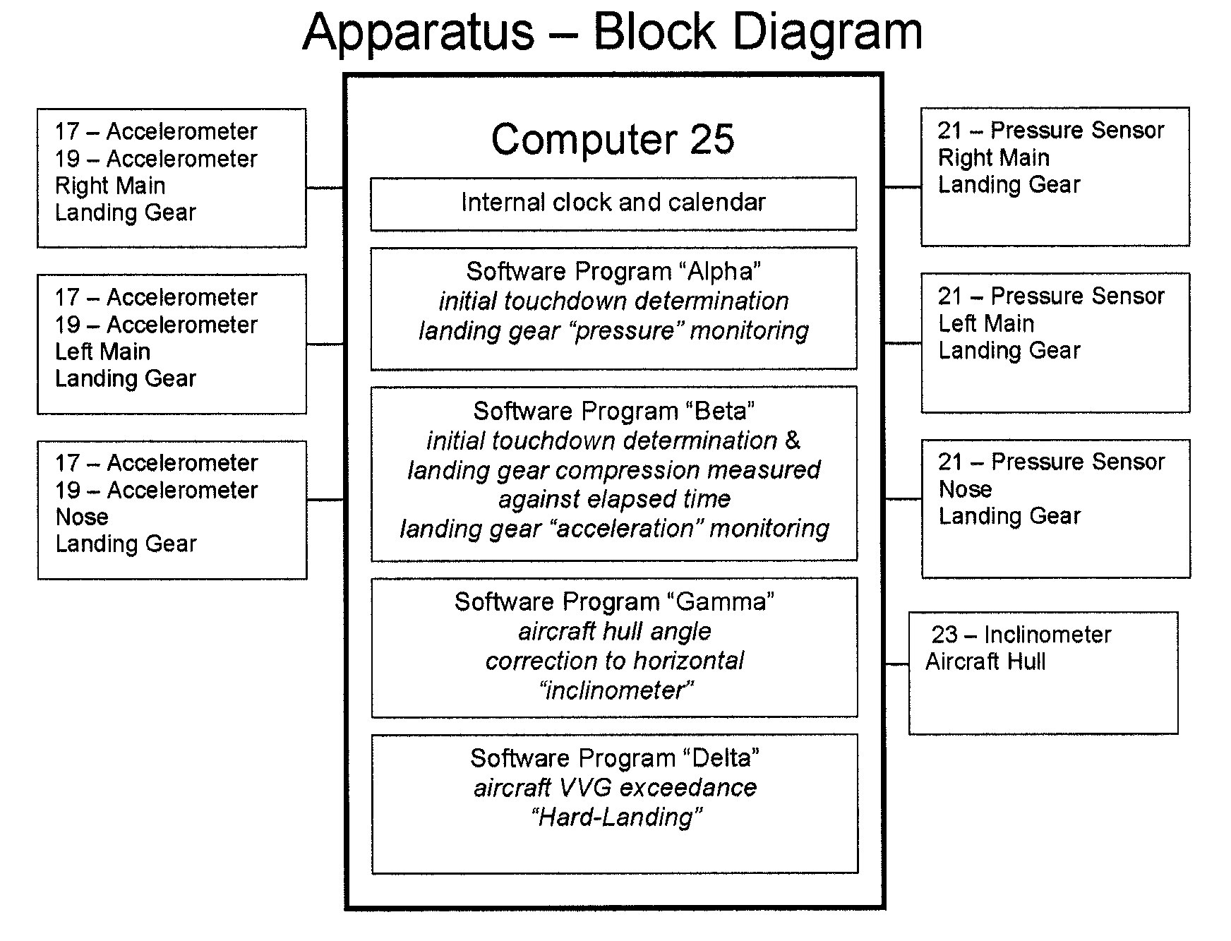
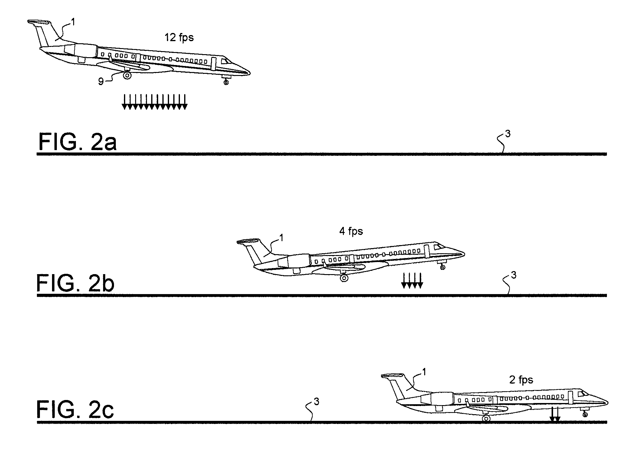
[0108]The present invention measures and determines the compression rate experienced by each landing gear strut on initial contact with the ground. The strut is monitored for compression so as to confirm that the aircraft has come into contact with the ground and also to determine the rate of strut compression and the aircraft vertical descent velocity.

[0109]The present invention detects initial and continued compression of the landing gear strut by rapidly monitoring internal strut pressure, prior to initial contact with the ground, as well as throughout the remainder of the landing event. Dual measurements of vertical acceleration are also monitored at a very rapid rate and are stored within a computer which is part of the system. The computer then compares changes in strut pressure to determine the amount of strut...


PUM


Abstract

A system for use in monitoring, measuring, computing and displaying the rate of compression of aircraft landing gear struts, experienced while aircraft are executing either normal or hard landing events. Further by measuring the vertical compression rate of the landing gear strut, thus with aircraft hull angle correction to horizontal, determining the vertical sink-rate of the aircraft, as it comes into initial contact with the ground. Accelerometers are attached to opposing sides of a compressible landing gear strut, monitoring and measuring parallel data streams; then identifying differential acceleration data streams, which computed through mathematical algorithms measure the collapse rate of the landing gear strut. Pressure sensors are attached to the working pressure within the landing gear strut, so to monitor in-flight landing gear strut pre-charge pressure, until such time as the pre-charge pressure suddenly increases, to detect the aircraft has come into initial contact with the ground. A method of operating an aircraft at an increased maximum landing weight limitation.

Description

BACKGROUND OF THE INVENTION[0001]An aircraft is typically supported by plural pressurized landing gear struts. Designs of landing gear incorporate moving components which absorb the impact force of landing. Moving components of an aircraft landing gear shock absorber are commonly vertical telescopic elements. An alternate type of landing gear incorporates a trailing arm design which forms a triangle shape, where the main supporting body of the landing gear is hinged with a trailing arm, and a typical telescopic shock absorber functions as the third side of the triangle. The telescopic shock absorber of both types of landing gear comprise internal fluids, both hydraulic fluid and compressed nitrogen gas, and function to absorb the vertical descent forces generated when the aircraft lands.[0002]Prior to a landing event, as the aircraft descends towards the runway, the landing gear is deployed. Each of the landing gear maintains an internal pre-charge pressure within the telescopic sho...

Claims


Application Information

Patent Timeline
IPC IPC(8): G05D1/00
CPCB64C25/00G05D1/0066G05D1/0083B64D2045/008
Inventor NANCE, C. KIRK
Owner NANCE C KIRK
Why Eureka
Try Eureka