Flexible airflow separator to reduce aerodynamic noise generated by a leading edge slat of an aircraft wing

a technology of leading edge slats and airflow separators, which is applied in the direction of airflow influencers, fuselages, transportation and packaging, etc., can solve the problems of aerodynamically generated slat gap noise that can reach or exceed the noise level magnitude of jet engines, and the effect of vortex noise is significant potential noise sour

Inactive Publication Date: 2003-12-11
DEUTSCHES ZENTRUM FUER LUFT & RAUMFAHRT EV +1
View PDF0 Cites 48 Cited by
  • Summary
  • Abstract
  • Description
  • Claims
  • Application Information

AI Technical Summary

Problems solved by technology

The air flowing through this gap or slot achieves the desired increase of the generated lift, but simultaneously also leads to an increased noise generation.
This aerodynamically generated slat gap noise can actually reach or exceed the noise level magnitude of the jet engines, when the engines are sharply throttled back during a landing approach.
In view of the above, it has long been a serious problem and the subject of substantial research in the field of aircraft design, to reduce the aerodynamically generated noise of the air flowing over various aircraft structures, and especially the extended high-lift auxiliary devices, and particularly the extended leading edge slats.
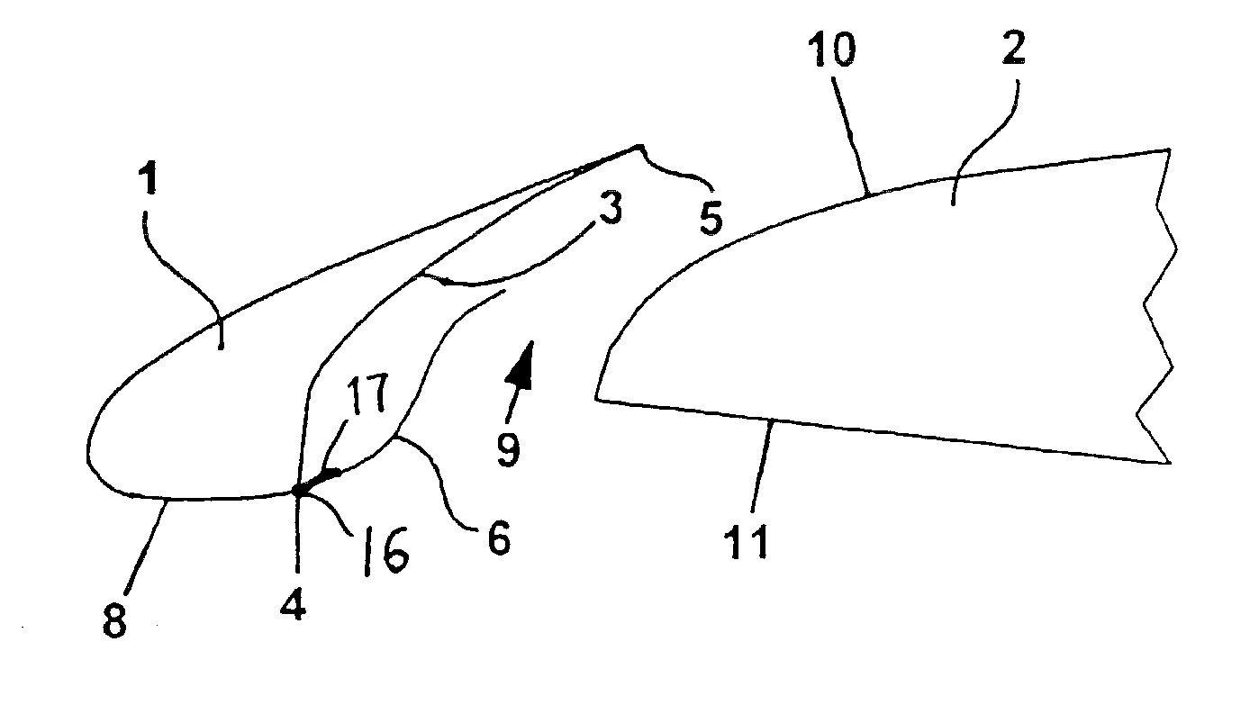
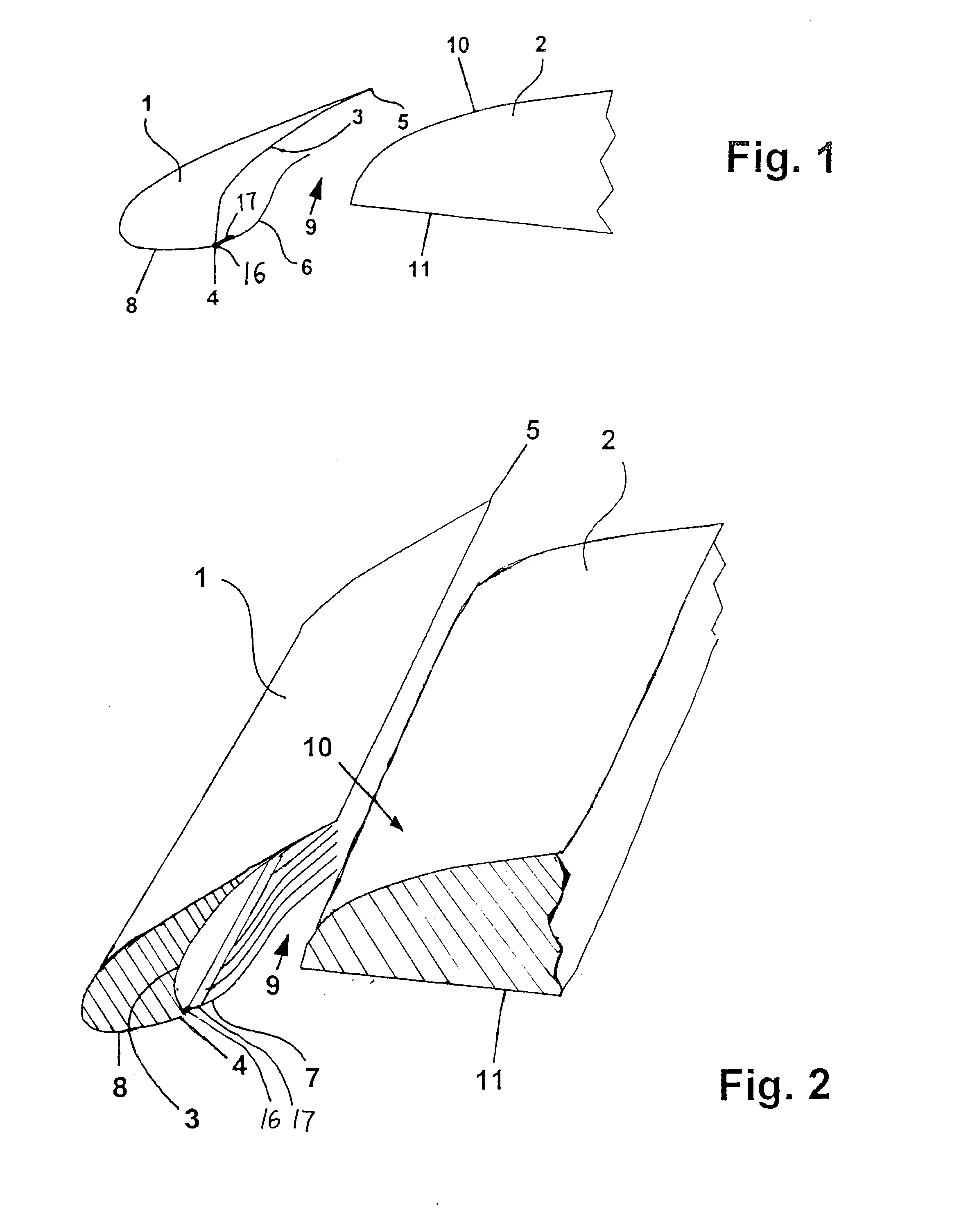
This entrapped eddy vortex is a significant potential noise source.
These turbulence cells continuously become entrained in the accelerated gap flow, whereby the major noise is generated, especially due to the further flow of these turbulence cells past the upper rear or trailing edge of the slat and then over the upper surface of the main wing.
Although the above described arrangement of a hinged airflow guide plate may have achieved noise reductions in wind tunnel tests, this solution is not expected to find substantial use in real world applications, in view of practical considerations and difficulties in the actual practice thereof.
However, that is not the proper curvature contour of the guide plate for its operation.
Furthermore, the retracted position of the slat does not provide sufficient space to allow such a rigidly configured guide plate to be stored between the retracted slat and the nose area of the main wing.
On the other hand, if the guide plate is to be flexible, to adapt itself to the curvature of the available space in the retracted and stowed condition of the slat, then such a flexible guide plate would not have sufficient strength and stiffness to durably withstand the significant aerodynamic forces that arise from the airflow through the slat gap in the extended condition of the slat.
As a result, the guide plate will tend to flutter, with the end result of radiating noise, which is directly contrary to the intended noise reduction effect.
Furthermore, a pivotally connected or hinged guide plate requires additional mechanically movable parts, which disadvantageously lead to an increase of the manufacturing, installation, maintenance and repair costs, as well as an increase of the total installed weight in the aircraft.
Another problem is that the transition from the lower surface of the slat to the hinge of the guide plate or separation surface must be free from contour discontinuities or jumps as well as open slots, which therefore requires very high fabrication and installation accuracy with low tolerances.
Another problem is that the metal guide plate or separation surface is subjected to considerable alternating forces that are initiated by the airflow.
Since this guide plate or separation surface is connected only to the bottom edge of the slat via the hinge joint, and no further supports or stiffening arrangements are provided, there is a significant danger that the guide plate or separation surface will be stimulated to oscillate or vibrate back and forth.
That would cause significant airflow disruption, drag, and additional noise.
Furthermore, since the contour of the rear surface of the slat, as well as the geometry of the air gap, varies over the span of the wing, the various elements of this guide plate or airflow separation surface must be formed with a taper or angled inclination over the span, which leads to additional complication of the retraction mechanism.
The situation of any fault or failure becomes especially critical, for example if the mechanism becomes blocked, because then the slat can no longer be retracted.
Nonetheless, the above discussed disadvantages would also apply to such an arrangement.
Additionally, there is a danger that such a covering of the concave curved inner surface or rear surface of the slat will form a resonance volume, which will actually lead to an increased noise radiation.
While this arrangement achieves a significant reduction of the aerodynamically generated noise, the system requires an active control arrangement, and the expandable displacement element is subject to aging degradation as well as wear and the like.
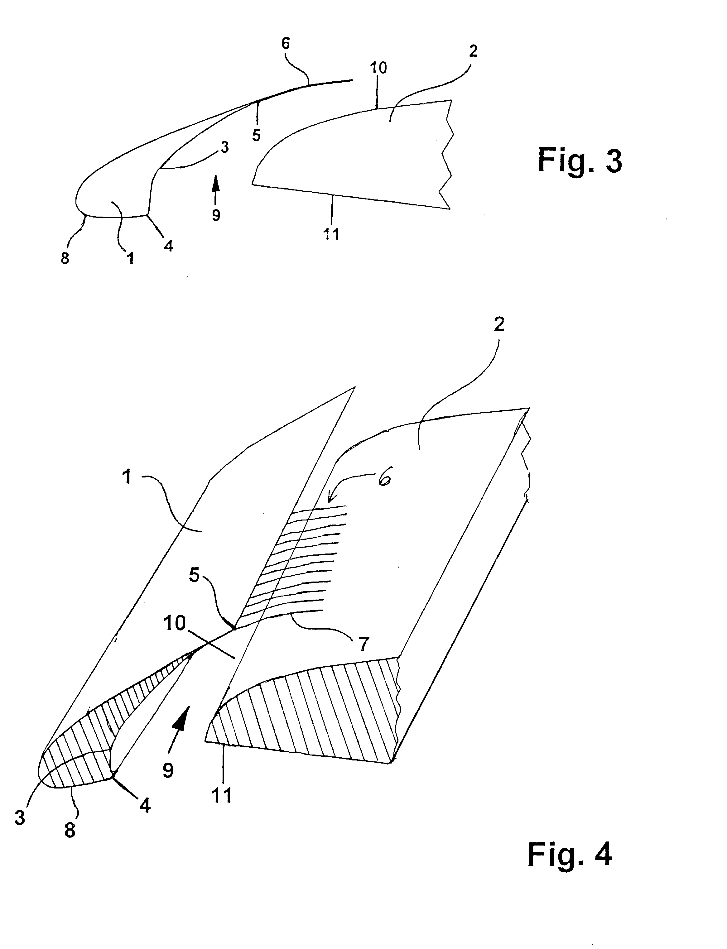
However, the density of the bristles is limited so that the bristles preferably do not form a closed or airtight separation surface, but instead allow a limited air permeability through the airflow separation surface, to provide a controlled pressure compensation between the entrapped eddy vortex and the smooth gap airflow on opposite sides of the separation surface.

Method used


Image

  • Flexible airflow separator to reduce aerodynamic noise generated by a leading edge slat of an aircraft wing
  • Flexible airflow separator to reduce aerodynamic noise generated by a leading edge slat of an aircraft wing
  • Flexible airflow separator to reduce aerodynamic noise generated by a leading edge slat of an aircraft wing

Examples


Embodiment Construction

[0029] For a general background understanding of the aerodynamic noise generation that is to be addressed by the present invention, reference is first made to FIG. 9, showing a conventional wing arrangement. As shown in FIG. 9, a conventional wing arrangement includes a leading edge slat 1 extended forwardly from the forward nose of a main wing body 2, for example of a commercial passenger transport aircraft. The slat 1 has a concave rearward surface 3, while the forward nose of the main wing body 2 has a convex surface, with a slat air gap 9 formed therebetween when the slat is in the extended position. An accelerated slat gap airflow flows from the underside 11 of the wing upwardly through the slat air gap 9 and over the upper surface 10 of the main wing body 2. This creates an increased lift generation. However, this also causes the formation of an entrapped eddy vortex 12 along the concave rear surface 3 of the slat 1.

[0030] This entrapped eddy vortex 12 generates and radiates a...


PUM


Abstract

A slat is selectively extended from a main wing body, with a concave rear surface of the slat facing a convex forward nose surface of the wing body, with a slat gap therebetween. At least one row of flexible bristles is movably arranged relative to the lower rear edge of the slat, to flexibly protrude up into the slat air gap. At least one row of flexible bristles is movably arranged along the upper rear edge of the slat to extend rearwardly over the slat air gap and the upper surface of the main wing body. The flexible bristles are flexibly self-positioning and self-contouring due to the aerodynamic forces acting thereon, to improve the air flow conditions through the slat gap, separate the slat gap airflow from an entrapped eddy vortex on the concave rear surface of the slat, and thereby reduce the aerodynamic noise generated along the slat gap.

Description

PRIORITY CLAIM[0001] This application is based on and claims the priority under 35 U.S.C. .sctn.119 of German Patent Application 101 57 849.0, filed on Nov. 24, 2001, the entire disclosure of which is incorporated herein by reference.[0002] The invention relates to an arrangement for reducing the aerodynamic noise generated by a leading edge slat of a main wing of a commercial passenger transport aircraft.BACKGROUND INFORMATION[0003] Modern commercial passenger transport aircraft are equipped with high-lift auxiliary devices that are typically deployed during take-off and / or landing phases of a flight in order to increase the lift generated during relatively low flight speeds. These high-lift auxiliary devices include leading edge slats and landing flaps, which are respectively movably connected to the leading edge area and the trailing edge area of a main wing, so as to be selectively extendible from or retractable to the main wing. In the extended or deployed positions, these high...

Claims


Application Information

Patent Timeline
Patent Type & Authority Applications(United States)
IPC IPC(8): B64C3/46B64C9/24B64C21/04B64C21/10B64C23/00B64C23/06B64D15/04
CPCB64C23/005B64C9/24
Inventor MAU, KNUTDOBRZYNSKI, WERNER
Owner DEUTSCHES ZENTRUM FUER LUFT & RAUMFAHRT EV
Why Eureka
Try Eureka