Integrated window belt system for aircraft cabins

a window belt and aircraft cabin technology, applied in the field of aircraft interior assemblies, can solve the problems of difficult to properly secure the panels to the aircraft, each component of the inner sidewall system has its own set of design problems, and the installation and removal of sidewall parts are expensive in terms of time and cost, and achieve the effect of convenient installation and rapid installation

Active Publication Date: 2006-10-10
THE BOEING CO
View PDF24 Cites 46 Cited by
  • Summary
  • Abstract
  • Description
  • Claims
  • Application Information

AI Technical Summary

Benefits of technology

[0016]An embodiment of the present invention provides an integrated window belt system that may easily be installed on the inboard side of an aircraft frame within the cabin along the structural windows in the outboard wall of the aircraft. The system provides an integrated set of components comprising a snap-in sidewall panel subsystem, a snap-fit window reveal subsystem, a thermo-acoustic insulation subsystem, enabling architecture system support bracketing subsystem, which may collectively eliminate multiple parts and fasteners, as well as the tedious efforts required to install them, by the use of snap-fit features. The thermo-acoustic insulation subsystem may be slightly compressed by the panels to provide vibration damping qualities as it interacts with the outer panel surface. The sidewall panel subsystem may be rapidly assembled and installed against the interior aircraft frame between a lower dado panel and an upper storage bins system, each of which extend longitudinally down the cabin. Each panel may be rapidly installed, removed for maintenance, and reconfigured without special tools. All components may be designed to interconnect by use of snap-fit attachments, as will be presently seen.
[0018]In another aspect of the present invention, a sidewall panel assembly is provided, where the assembly comprises a sidewall panel and a window reveal. The sidewall panel may have a panel opening, an inboard surface, an outboard surface, and a first fastener, where the first fastener may be integral with the sidewall panel and disposed to allow removable attachment of the sidewall panel to an aircraft frame. The window reveal may have a rim and an inwardly tapering perimeter, so that the window reveal may be sized for snug insertion through the panel opening, and the window reveal may be removably attached within the panel opening and against the inboard surface by a second fastener that is integral to the window reveal. When the sidewall panel is positioned for operational attachment on an interior of an aircraft frame with the panel opening generally opposing an outer window assembly in an outboard wall, the outboard edge of the window reveal may position both it and the sidewall panel into their operationally installed positions as the inward taper guides the outboard edge into a mating relationship with the outer window assembly.
[0021]In a further aspect of the present invention, a method of assembling a maintainable modular sidewall panel system within an aircraft cabin is provided, where the cabin has a floor and a plurality of frames extending upwardly from the floor, each frame having an inboard side and an outboard side, an outboard wall attached to an outboard side of the plurality of frames, the outboard wall with a plurality of structural openings extending longitudinally along and through the outboard wall and between the plurality of frames, the cabin having a dado panel extending longitudinally the length of the cabin adjacent to the floor and below the plurality of structural openings, the cabin further having an upper structure extending longitudinally the length of the cabin above the plurality of structural openings, each structural opening with an outer window assembly. The method comprises the following steps: installing brackets along the plurality of frames; inserting an outer window assembly within each structural opening, each outer window assembly having a inwardly protruding window forging; attaching a plurality of insulation foam blocks along the outboard wall; suspending the plurality of sidewall panels from the upper structure so that each sidewall panel conforms to the inboard side of the plurality of frames each sidewall panel having an upper edge and lower edge, each sidewall panel suspended along its upper edge for pivotal motion inwardly and outwardly about a horizontal axis along its upper edge, a selected number of the plurality of sidewall panels having at least one panel opening, each of the selected number longitudinally positioned so that each panel opening generally opposes one of the structural openings when the sidewall panel is aligned with the inboard side of the plurality of frames; inserting through each panel opening from the inboard side of the sidewall panel a window reveal with a rim and a inwardly tapering perimeter, the rim held against the inboard side of the sidewall panel by snap-fit fasteners and constrained from further insertion by the rim; and bringing the lower edge of the sidewall panel into attachment with the dado panel, thereby capturing the foam insulation blocks between the sidewall panel and the outboard wall and allowing the inwardly tapering perimeter of the window reveal to be guided into the window forging, wherein a tapering fit between the window forging and the inwardly tapering perimeter aligns the sidewall panel with the plurality of frames.

Problems solved by technology

Therefore, current inner sidewall systems have been constructed piecemeal of many numerous components, and this has made installation and removal expensive in terms of number of sidewall parts and time required to remove and replace them.
However, each component of an inner sidewall system has its own set of design issues.
Since the shock mounts are conventionally prelocated by being riveted to the aircraft frames prior to attaching the panels or insulation, it is sometimes difficult to properly secure the panels to the aircraft.
This is because either the tabs of the adjacent panels do not properly align with each other to permit simultaneous engagement by the bridge fasteners, or because the tabs do not align with the position of the bridge fastener; the position of the bridge fastener being fixed by the location of the mounting holes in the prelocated shock mount.
Furthermore, the lengthwise gap between the edges of the adjacent panels may be too small to accommodate a vertical trim strip, or the projecting screw fasteners may prevent the trim strip from being easily inserted in the gap.
This installation of the numerous brackets can be very labor intensive and time consuming; the sidewall must first be sanded and the adhesive must then be applied and allowed to cure for an extended period, before the window reveal can be affixed to the brackets.
In addition, fuel economy can be negatively affected as the brackets and adhesives add weight to the aircraft, which in turn adds to the operating cost of the aircraft.
In addition, the brackets can be very pliable and weak or brittle.
They may therefore be subject to increased maintenance and replacement costs.
Additionally, because there is quite a variation in affixing mechanisms between various airplane models, standardization of the window assemblies across airplane models is difficult.
Difficult access to whole or part of the window assembly makes standard window maintenance, like cleaning, expensive and time consuming.
Such methods must be used since the brackets cannot be precisely placed when they are affixed by adhesives.
This alignment operation is very tedious and exacting, and it leads to significant assembly costs because installers must take substantial time and care to precisely affix and adjust the brackets.
The installation and placement of insulation within the inter-sidewall space can also be difficult and time-consuming.
However, one disadvantage of this process is that the initial installation of such insulation involves extensive technician time in order to create and seal numerous penetrations in the insulation, to place the numerous brackets required for holding the insulation, and to attach the insulation to the brackets.
Another disadvantage is that, because of the limp nature of traditional insulation, many penetrations must be made for supporting brackets, which in turn can cause numerous gaps in the insulation.
These gaps greatly diminish the ability of such insulation to reduce noise since they create flanking paths though which noise may efficiently transmitted.
Still another disadvantage is that the numerous brackets increase the weight of the aircraft and must themselves be affixed to the frames and exterior wall of the fuselage, which further increases technician time.
When the insulation layer must be removed for maintenance at some point along the cabin wall, the technician must again spend a significant amount of time removing and reinstalling the insulation layer.

Method used


Image

  • Integrated window belt system for aircraft cabins
  • Integrated window belt system for aircraft cabins
  • Integrated window belt system for aircraft cabins

Examples


Embodiment Construction

[0029]The following detailed description is of the best currently contemplated modes of carrying out the invention. The description is not to be taken in a limiting sense, but is made merely for the purpose of illustrating the general principles of the invention, since the scope of the invention is best defined by the appended claims.

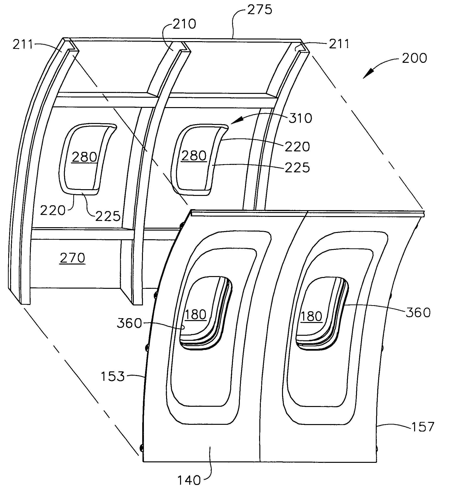
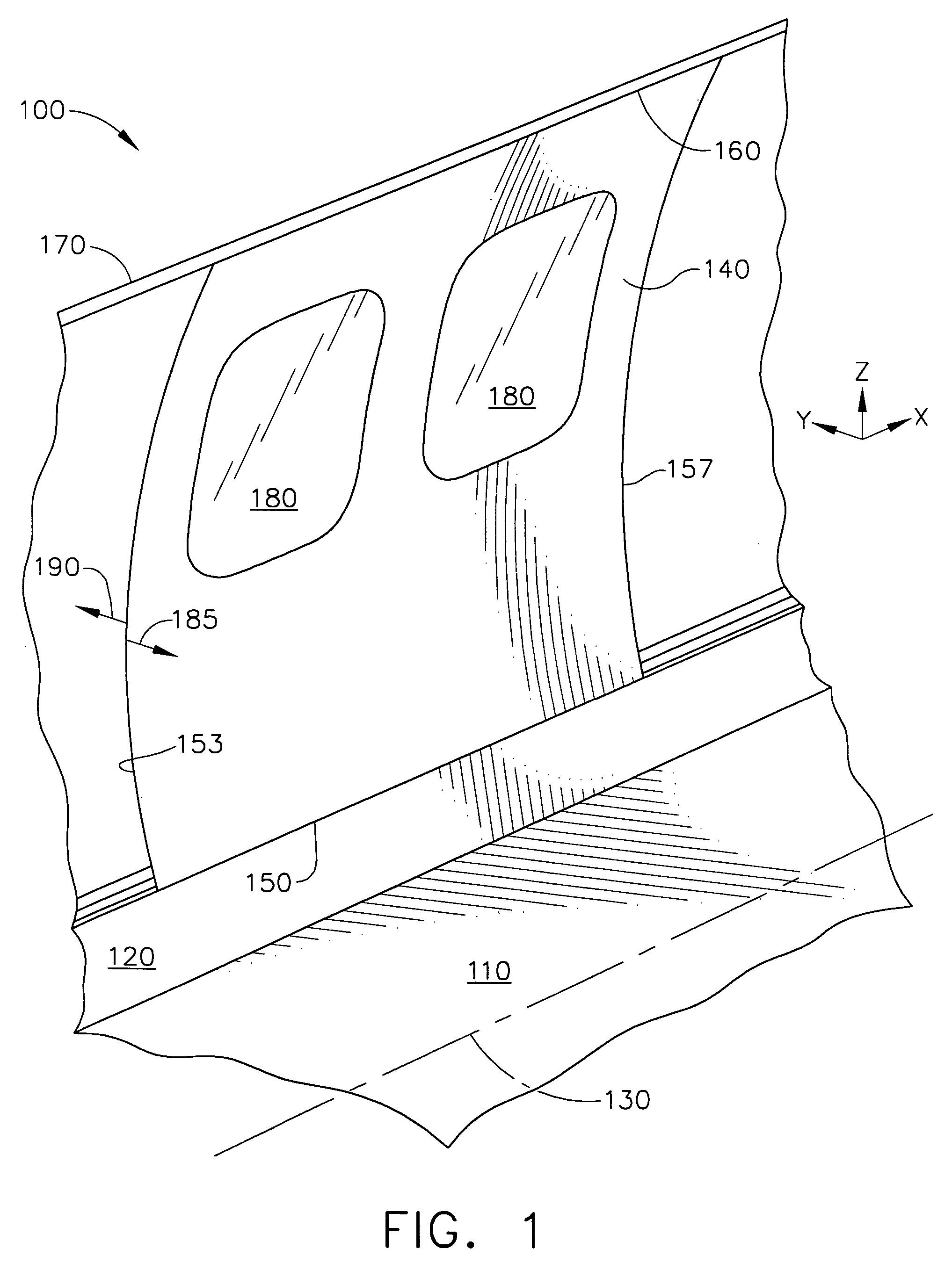
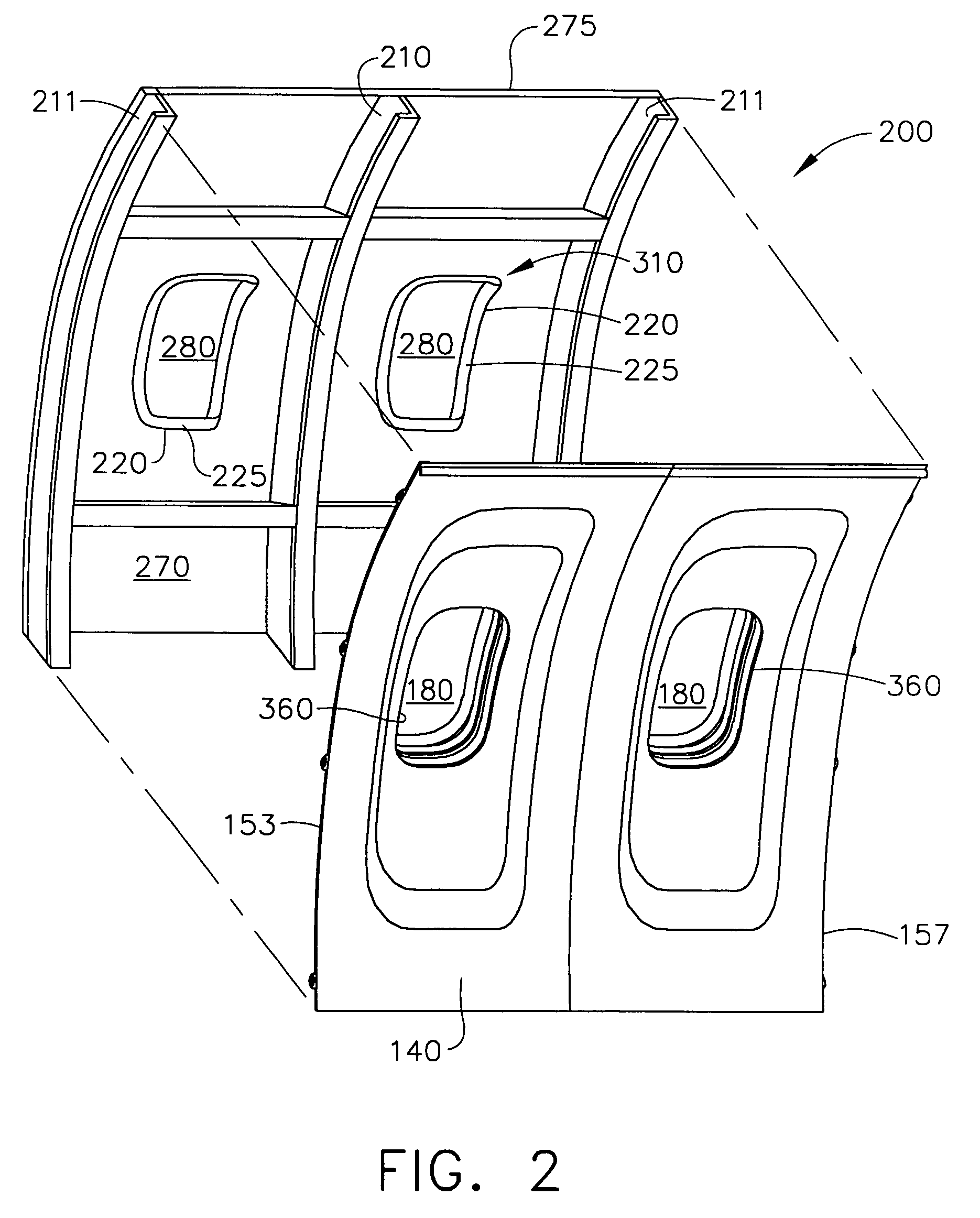
[0030]For ease of understanding the orientation in the drawings, the terms “inside”, “inboard”, and “interior” shall refer a direction oriented from the viewpoint of a person standing within the cabin of the aircraft, and the terms “outside”, “outboard”, and “exterior” shall refer to a direction oriented from the viewpoint of a person outside of the cabin observing the aircraft. Thus, a sidewall trim panel will have an interior side and an exterior side, where the interior side is that surface of the installed panel as seen by a person within the cabin of the aircraft and the exterior side is that surface of the installed panel that is seen by a person ...


PUM


Abstract

A system and a method is provided for fitting an aircraft cabin with modular sidewall panels, window reveals, and foam insulation blocks in an integrated manner. The system comprises a sidewall panel which may have one or more openings therethrough to receive a window reveal held by snap-fit fastenings. The bezel of the window reveal may be held by snap-fit fasteners for easy removal to allow removal and cleaning of the inner dust cover disassembly of the sidewall panel. Foam insulation blocks may be molded to fit in the cavity between the outer wall of the aircraft and the sidewall panels, held in place by compressive pressure between the frames of the airframe. The outer extent of the window reveal is tapered inwardly to guide the window reveal to mating contact with an outer window assembly in the aircraft fuselage without further adjustment of the sidewall panel.

Description

BACKGROUND OF THE INVENTION[0001]The present invention generally relates to interior assemblies for aircraft, and more particularly to a system of sidewall panels, window assemblies, and insulation structures for installation upon a cabin wall within the interior of an aircraft.[0002]Fabrication of a commercial aircraft typically consists of building an airframe (sometimes referred to as a primary structure or fuselage) consisting of a series of vertically oriented frames, or ribs, that encircle a cabin area for transporting personnel and cargo. The outboard side of the frames is covered with an outboard wall or skin and the inboard side of the frames in the cabin area may similarly be covered with sidewall trim panels. Along the outboard wall and between the frames, other aircraft components such as insulation, electrical conduits, ventilation ducting, control mechanisms, and the like may be installed, so that they may be enclosed between the outboard wall and the sidewall trim pan...

Claims


Application Information

Patent Timeline
Patent Type & Authority Patents(United States)
IPC IPC(8): B64C1/14
CPCB64C1/066B64C1/1484B64D2011/0046Y02T50/46Y02T50/40
Inventor NOVAK, KEITH H.MUMM, ROBERT W.HILLS, KAREN L.WONG, JOE S.PARE, SHAWN M.MILLER, JULIA W.WAIDNER, ART
Owner THE BOEING CO
Why Eureka
Try Eureka