Spatial information detection device

Active Publication Date: 2013-12-12
PANASONIC SEMICON SOLUTIONS CO LTD
View PDF2 Cites 5 Cited by
  • Summary
  • Abstract
  • Description
  • Claims
  • Application Information

AI Technical Summary

Benefits of technology

[0006]Further, a device designed to provide a light projection period in which the signal light is emitted to the space and a non-light projection period in which no signal light is emitted to the space is known as the spatial information detection device detecting the spatial information such as a reflectance or an absorbance of an object present in a space, a reflectance or an absorbance of a medium in a space, and presence or absence of an object in a space

Problems solved by technology

Therefore, there arises a problem that accurate detection of the spatial information may be prevented.
Consequently, the

Method used


Image

  • Spatial information detection device
  • Spatial information detection device
  • Spatial information detection device

Examples


first embodiment

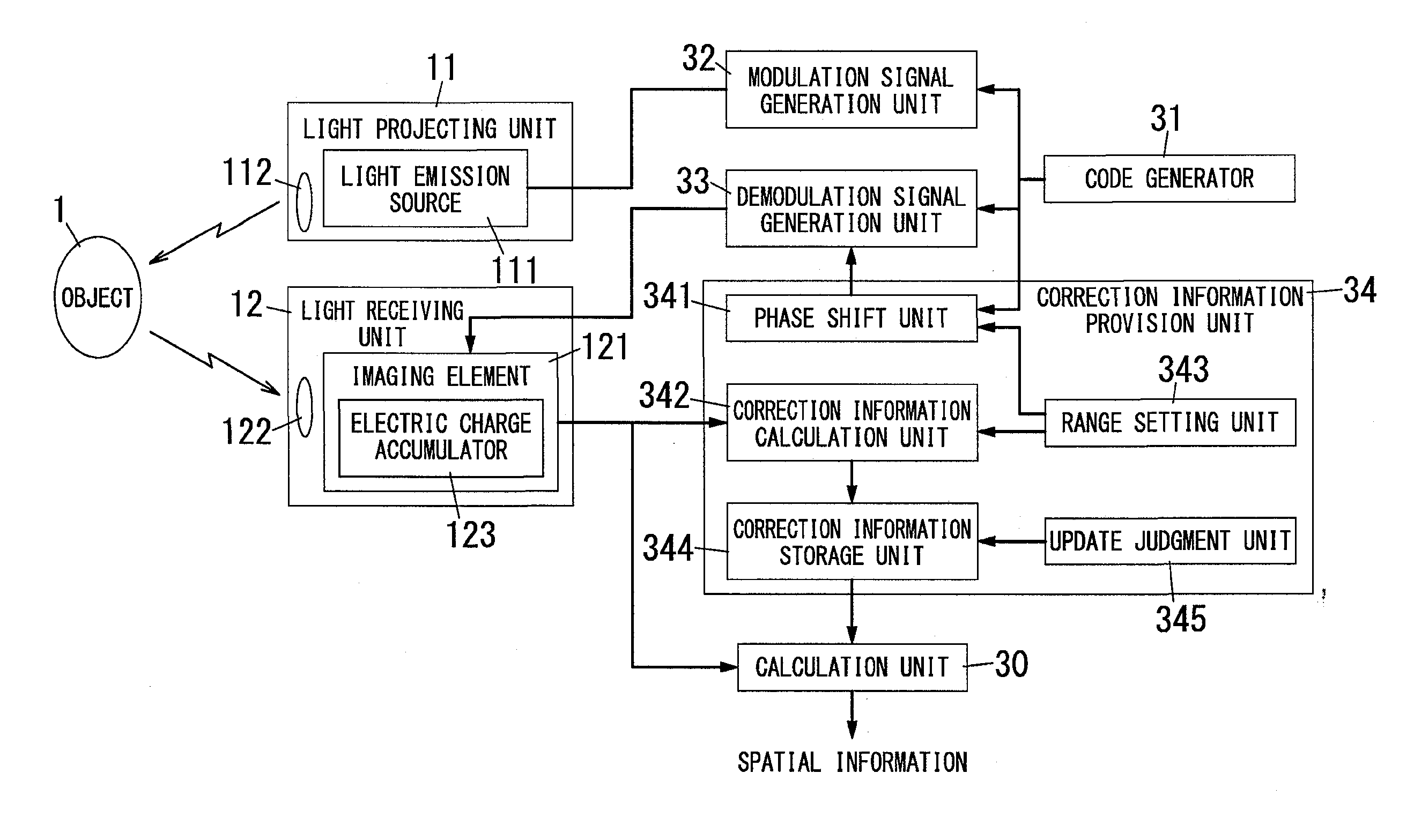
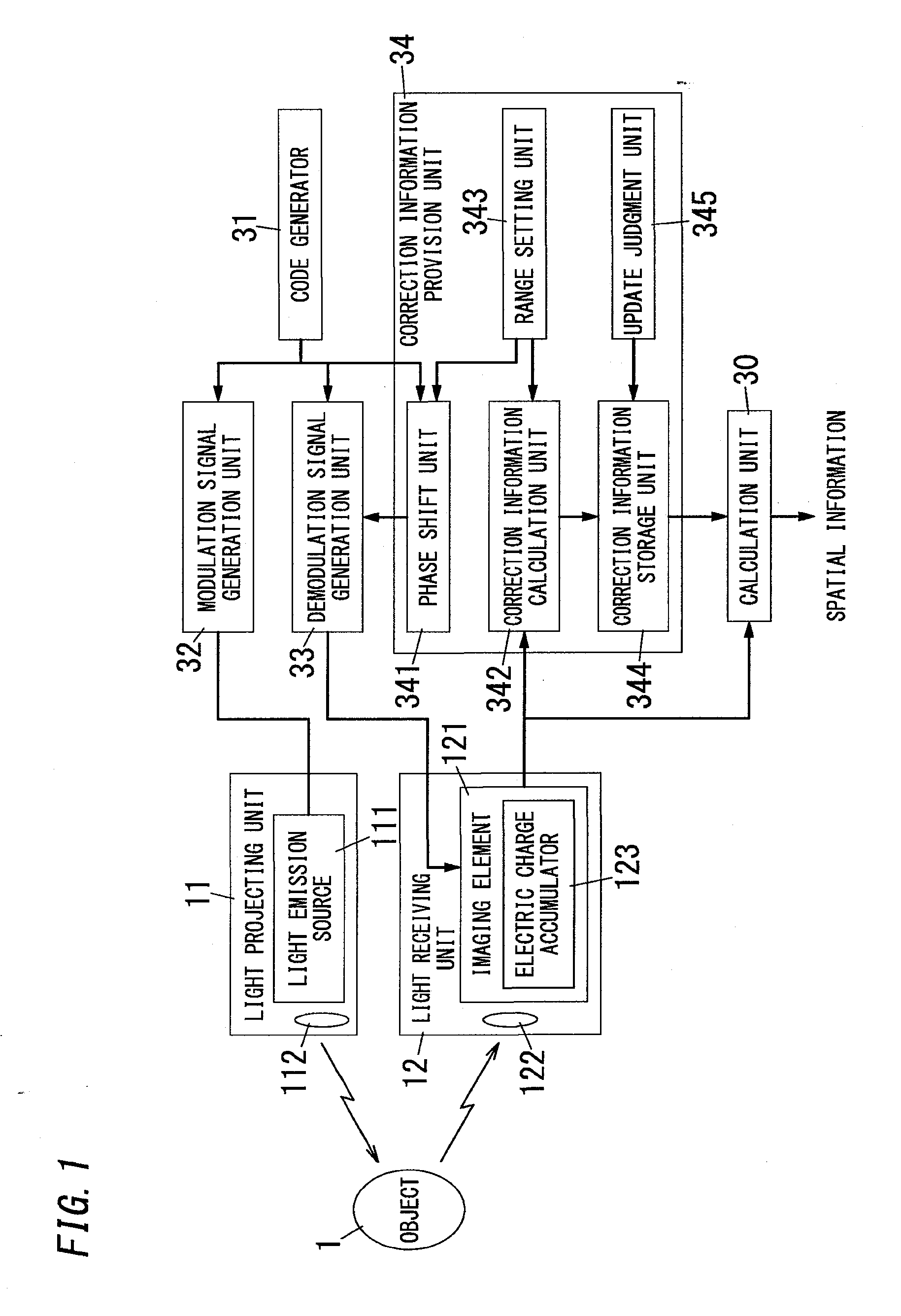
[0105]As shown in FIG. 1, the spatial information detection device of the present embodiment includes the light projecting unit 11, the light receiving unit 12, the calculation unit 30, the code generator 31, the modulation signal generation unit 32, the demodulation signal generation unit 33 and a correction information provision unit 34. In brief, the present embodiment includes the correction information provision unit 34 in addition to the basic configuration for generating the distance image.

[0106]The correction information provision unit 34 provides, to the calculation unit 30, the correction information gA and gτ used in calculation of the distance value (spatial information). The correction information provision unit 34 has a function of calculating the correction information gA and gτ in addition to a function of providing the correction information gA and gτ to the calculation unit 30. In brief, the correction information provision unit 34 is configured to generate the cor...

second embodiment

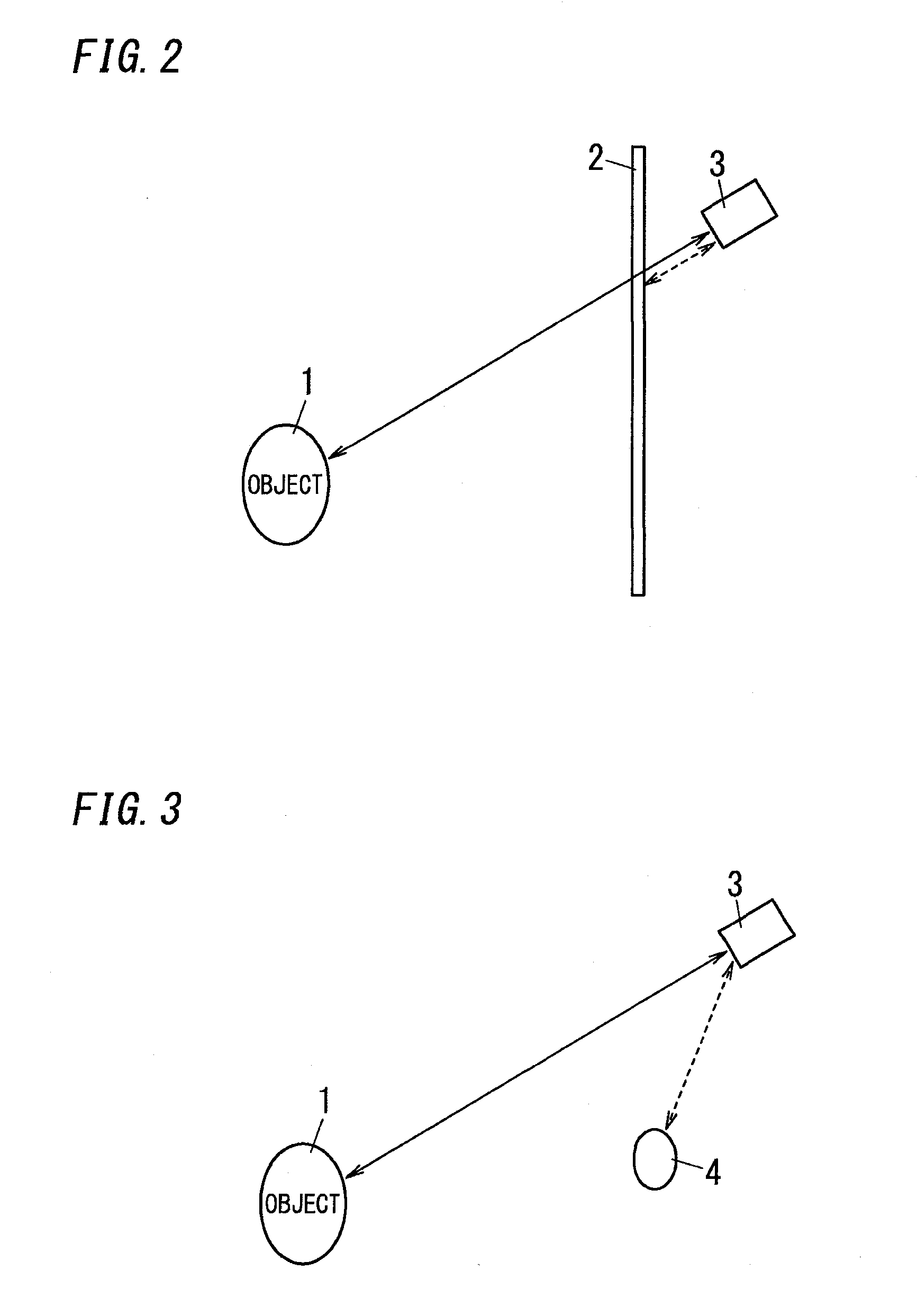
[0163]In the first embodiment, the explanation is made to the technique of calculating the correction information gA and gτ with regard to the range in which only the transparent object 2 exists. In a process of calculating the correction information gA and gτ, it may be difficult to make a situation where only the transparent object 2 exists. The following explanation is made to a technique of acquiring the correction information gA and gτ relating to the transparent object 2 by use of the fact that the distance from the distance measurement device to the transparent object 2 is shorter than the distance from the distance measurement device to the space selected as the target for distance measurement.

[0164]When the transparent object 2 is closer than the object 1 is, the amount A0 of the electric charges related to the light reflected by the object 1 and the amount gA0 of the electric charges related to the light reflected by the transparent object 2 are varied with a change in the...

third embodiment

[0181]In the aforementioned embodiments, the operation of the distance measurement device under the existence of the transparent object 2 is described. However, also in the intensity measurement device, with using the correction information gA and gτ, it is possible to eliminate the electric charges caused by the existence of the transparent object 2 and calculate the spatial information. Hence, the spatial information detection device of the present embodiment serves as the intensity measurement device.

[0182]For example, when the transparent object 2 is absent, the following formula (28) is available in the light projection period to the object 1 which is present in the region determined by the range in which the time difference τ is equal to 0 or more and is equal to Tc or less. Note that, the suffix “L” is attached to denote the amount of the electric charges relates to the light projection period, and the suffix “D” is attached to denote the amount of the electric charges relate...


PUM


Abstract

The spatial information detection device emits, to a space including an intended area, signal light defined as light modulated with a modulation signal defined as a square wave signal having high and low level periods appearing alternately, each of the periods having its length randomly selected from integral multiples of a unit time period. The device generates signal electric charges by accumulating electric charges generated in response to light from the space in a collection time period determined by a demodulation signal defined as a signal having the same waveform as that of the modulation signal or that of the inverted modulation signal. The device corrects, using correction information regarding an effect caused by light from an unintended area, the amount of signal electric charges as an amount of intended electric charges produced in response to light from the intended area, thereby generating spatial information.

Description

TECHNICAL FIELD[0001]The present invention relates to spatial information detection devices and particularly to an active type spatial information detection device which emits light to a space to be detected and receives light from the space in order to detect spatial information such as a distance to an object present in this space, a reflectance or an absorbance of an object present in this space, a reflectance or an absorbance of a medium in this space, and presence or absence of an object in this space.BACKGROUND ART[0002]In the past, there have been proposed active type spatial information detection devices configured to detect spatial information by means of emitting light to a space to be searched and receiving light from the space. These kinds of spatial information detection devices detect the spatial information such as a distance to an object present in a space, a reflectance or an absorbance of an object present in a space, a reflectance or an absorbance of a medium in a...

Claims


Application Information

Patent Timeline
IPC IPC(8): G01B11/02G01S7/4912G01S7/4915G01S17/32G01S17/894
CPCG01S7/4912G01S17/32G01S7/4915G01B11/02G01S17/89G01S17/894
Inventor MURAKAMI, KENICHIHASHIMOTO, YUSUKE
Owner PANASONIC SEMICON SOLUTIONS CO LTD
Why Eureka
Try Eureka