Microscope and method for determining a measuring location of a microscope

Pending Publication Date: 2021-07-22
CARL ZEISS MICROSCOPY GMBH
View PDF0 Cites 1 Cited by
  • Summary
  • Abstract
  • Description
  • Claims
  • Application Information

AI Technical Summary

Benefits of technology

[0013]Effects of the invention come particularly to bear if an overview camera for recording the overview image and a microscope objective are situated on opposite sides (above/below) of the sample carrier and the sample carrier does not have a negligible height. An example will be explained below to ease understanding. As a rule, an overview image is recorded at an angle to a measuring direction of the microscope. By way of example, a viewing direction of an overview camera can be at an angle to the optical axis of an objective of the microscope. The measurement location of the microscope can be located on the optical axis of the objective. However, in a recorded overview image, the image coordinates in the overview image through which the optical axis of the objective extends are not readily clear. These depend on the distance of the sample carrier from the overview camera, which is variable as a matter of principle. By way of example, different sample carriers (e.g., microtiter plates) can have different height dimensions, as a result of which the distance between the recorded microtiter plates and an overview camera is variable. Particularly if the overview camera is at an angle to the optical axis, the image coordinates of the measurement location in the overview image have a pronounced dependence on the height of the sample carrier or on the relative position thereof with respect to the overview camera. To take this dependence into account, a homography for the currently present sample height can be ascertained by way of the invention. As a result of this ascertained homography, it is possible to take account of the effect of the sample height on the image coordinates of the measurement location in the overview image.
[0014]A homography can be understood to mean a description or calculation rule relating to how points in one plane are perspectively imaged or projected into another plane. By way of example, an ascertained homography can be formed by a matrix, in particular a 3×3 matrix. It is possible to ascertain a homography which allows the overview image to be converted into a plan view image. This homography depends on the sample height, as explained above.
[0015]If a plan view image as output image is calculated from the overview image with the aid of the ascertained homography, the effect of the sample height on the image coordinates was removed in the output image. Independently of the specific sample height, the image coordinates of the measurement location of the microscope can always be the same in these output images. The values of the image coordinates of the measurement location can be specified in a plan view image. By way of example, the image coordinates at which the measurement location is situated in plan view images can be stored in a memory. Alternatively, these image coordinates for plan view images can also be calculated with the aid of known microscope parameters. Now, the measurement location can be identified by virtue of a calculated plan view image being used as a derived output image and the specified image coordinates, or the image coordinates stored in the memory, being identified herein as the measurement location.
[0016]As an alternative to the calculation of a plan view image from the overview image, the ascertained homography can also

Problems solved by technology

In this case, in particular, it is difficult for the user to reliably recognize the well or the measurement location at which an objective of the microscope is directed.
If manual stands are used, in which the sample carrier is moved by hand or using a xy-stage, there is, as a rule, no helpful information available about the sample stage

Method used


Image

  • Microscope and method for determining a measuring location of a microscope
  • Microscope and method for determining a measuring location of a microscope
  • Microscope and method for determining a measuring location of a microscope

Examples


Embodiment Construction

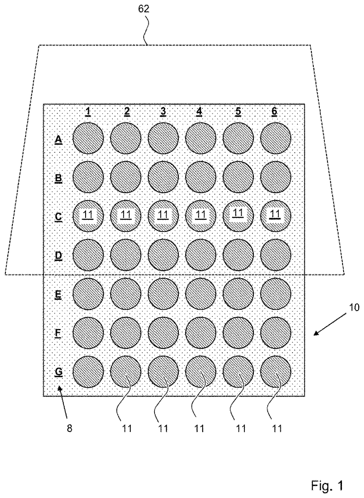
[0062]FIG. 1 schematically shows a sample carrier 10 with a plurality of sample vessels 11. In the illustrated example, this is a microtiter plate with a plurality of wells, wherein any other container could also be possible as a sample vessel 11. In this example, the sample vessels 11 are arranged in columns and rows, wherein a row label 8 specifies the various rows A-G and a column label specifies columns 1-6. The microscope is used to successively examine (the sequence is not mandatory) the various sample vessels 11 and record a microscope image in each case. In the process, there is a need for reliable documentation as to the sample vessel 11 to which the recorded microscope images belong.

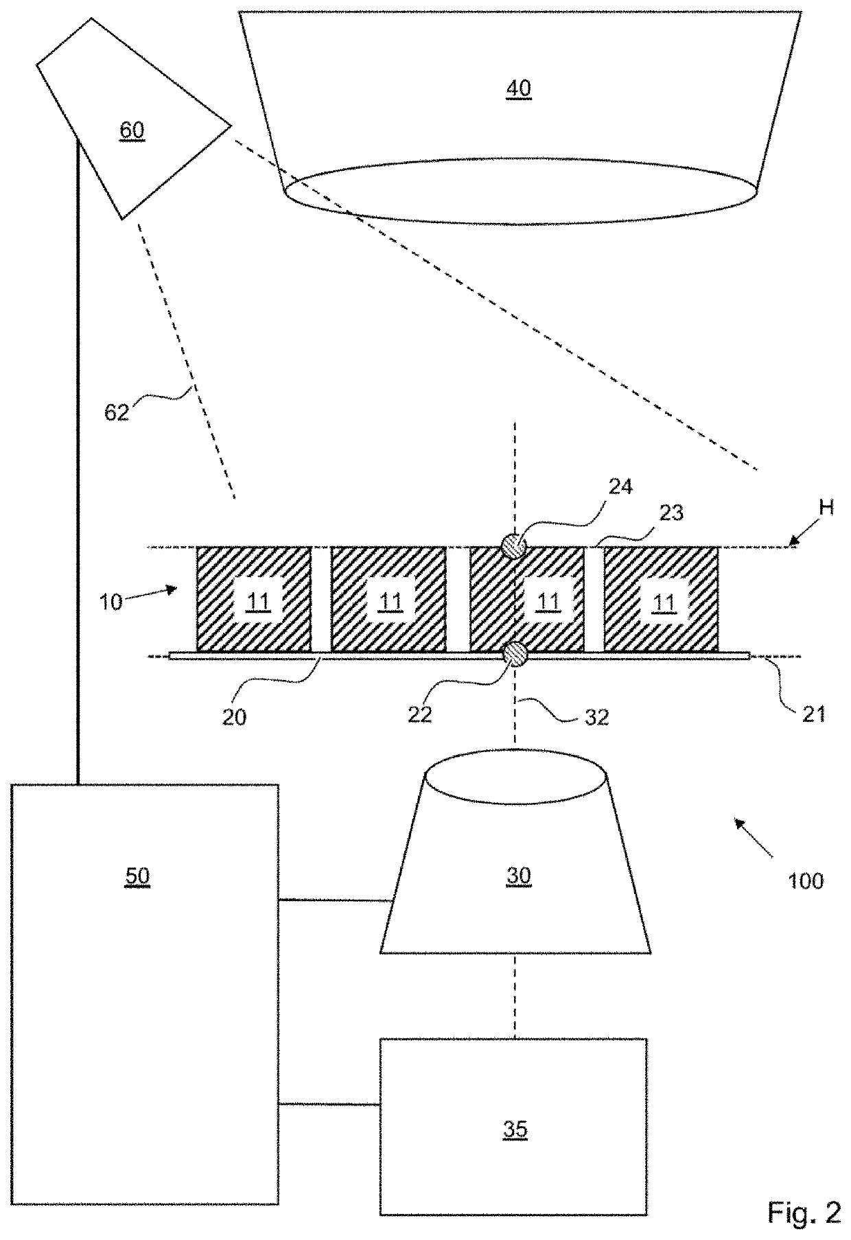
[0063]This is achieved by a microscope 100 according to the invention, as is shown in exemplary fashion in schematic FIG. 2. The microscope 100 comprises a sample stage or microscope stage 20, on which the sample carrier 10 is positioned. As described, the sample carrier 10 comprises a pluralit...


PUM


Abstract

An overview image of a sample carrier is obtained in a method for ascertaining a measurement location of a microscope. A mapping or homography is determined, by means of which the overview image is perspectively convertible into a plan view image on the basis of a height of the sample carrier. The measurement location is identified, with the aid of the determined mapping/homography, in the overview image or in an output image derived therefrom.

Description

REFERENCE TO RELATED APPLICATIONS[0001]The current application claims the benefit of German Patent Application No. DE 10 2020 101 191.1, filed on 20 Jan. 2020, which is hereby incorporated by reference.FIELD OF THE DISCLOSURE[0002]The present disclosure relates to a microscope and a method for ascertaining a measurement location of a microscope.BACKGROUND OF THE DISCLOSURE[0003]A sample carrier is positioned on a sample stage in conventional microscopes. The sample carrier can comprise a plurality of sample vessels and can be formed, for example, by a chamber object carrier (multi-well chamber slide) or a multi-well plate with wells. In this case, in particular, it is difficult for the user to reliably recognize the well or the measurement location at which an objective of the microscope is directed. If manual stands are used, in which the sample carrier is moved by hand or using a xy-stage, there is, as a rule, no helpful information available about the sample stage position.[0004]...

Claims


Application Information

Patent Timeline
IPC IPC(8): G06T7/73G01B11/00G06T7/11G06T7/80G02B21/36
CPCG06T7/73G01B11/002G06T2207/10056G06T7/80G02B21/36G06T7/11G06T3/0031G06T7/74G06N20/00G02B21/34G02B21/00G06T7/33G06T2207/30072G06T2207/30244G02B21/367
Inventor AMTHOR, MANUELHAASE, DANIELGÖGLER, MICHAEL
Owner CARL ZEISS MICROSCOPY GMBH
Why Eureka
Try Eureka