
Systems and methods of using absorptive imaging metrology to measure the thickness of ophthalmic lenses

Active Publication Date: 2018-02-01
JOHNSON & JOHNSON VISION CARE INC
View PDF5 Cites 2 Cited by
  • Summary
  • Abstract
  • Description
  • Claims
  • Application Information

AI Technical Summary

Benefits of technology

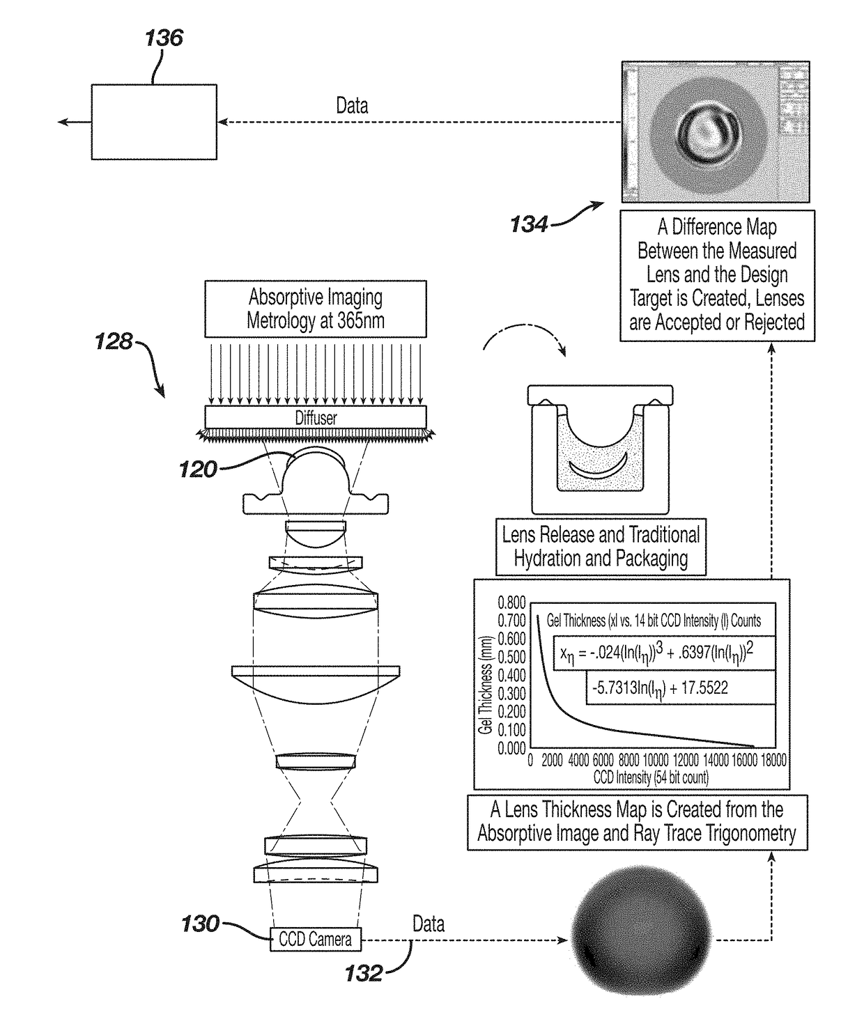
The patent text describes an absorptive imaging system that uses mathematical formulations and calibration to convert image intensity data to media thickness. This system includes digital imaging devices that capture thickness measurements and an entire surface profile of an object being measured, such as an ophthalmic lens. These measurements are used to determine how well a manufactured article matches its intended design, and the system may adjust how subsequent lenses are made based upon the thickness measurement feedback data. The patent text also discusses the issue of optical confusion, which can occur when collecting intensity data for a lens. This can cause the algorithm to interpret it as intensity attenuated thickness, and the use of integrating sphere illumination can improve the accuracy of these measurements.

Problems solved by technology

These efforts typically require the use of complex, multi-station systems, which are expensive, slow, and involve extreme positioning requirements.
As such, these systems are not suitable for mass production, and in-line use.
This approach, however, is expensive and requires precisely aligning the components to the sensor's optical axis.
This system is not capable of measuring rapid changes in surface topology (i.e., large power changes) and therefore is limited to only optic zone measurement of the lens.
The system is also expensive, requires a separate center thickness measurement station, is relatively slow (e.g., 45 seconds per measurement), and requires precise alignment and part placement.
This system is also expensive, slow (e.g., five minutes per measurement), susceptible to data dropout in steep topologies of the lens, is difficult to maintain, and is not suitable for in-line use.
A limitation of this system is that it cannot perform “dry” part measurements and requires lenses to be hydrated prior to measurement and fully immersed in a quiescent pool of liquid during measurement.
Due to expensive and rigid environmental controls, the system is typically found in centralized, quality control locations that require cumbersome procedures for submitting samples for testing and obtaining results.
As a result, the interferometer-based system is not suitable for in-line use.
The interferometer system also has some lens presentation issues.
Moreover, it is difficult for the Clover system to measure non-round lenses, and lenses that lay in a package in a tilted or partially curled configuration.

Method used


Image

  • Systems and methods of using absorptive imaging metrology to measure the thickness of ophthalmic lenses
  • Systems and methods of using absorptive imaging metrology to measure the thickness of ophthalmic lenses
  • Systems and methods of using absorptive imaging metrology to measure the thickness of ophthalmic lenses

Examples


Embodiment Construction

[0119]In the specification, various terms may be used for which the following definitions apply:

[0120]“Actinic Radiation” as used herein, refers to radiation that is capable of initiating a chemical reaction.

[0121]“Arcuate” as used herein, refers to a curve or bend like a bow.

[0122]“Beer's Law” as referred to herein and sometimes referred to as “Beers-Lambert Law” is: I(x) / I0=exp (-αcx), wherein I(x) is the intensity as a function of distance x from the irradiated surface, l0 is the incident intensity at the surface, α is the absorption coefficient of the absorbing component, and c is the concentration of the absorbing component.

[0123]“Collimate” as used herein means to limit the cone angle of radiation, such as light that proceeds as output from an apparatus receiving radiation as an input; in some embodiments the cone angle may be limited such that proceeding light rays are parallel. Accordingly, a “collimator” includes a apparatus that performs this function and “collimated” desc...


PUM


Abstract

A method of measuring the thickness of an ophthalmic lens includes providing an ophthalmic lens having a light absorptive component, and passing light having a wavelength through the ophthalmic lens whereupon the light absorptive component absorbs some of the light as the light passes through the ophthalmic lens. After the light has passed through the ophthalmic lens, the light is used to generate a digital image for the ophthalmic lens that has pixel intensity data that corresponds to the shape of the ophthalmic lens. Information about the light prior to passing through the ophthalmic lens, the light absorptive component of the ophthalmic lens, and the pixel intensity data is used to calculate a thickness profile for the ophthalmic lens.

Description

CROSS REFERENCE TO RELATED APPLICATIONS[0001]The present patent application claims benefit of U.S. Provisional Application No. 62 / 355,753, filed Jun. 28, 2016, the disclosure of which is hereby incorporated by reference herein.BACKGROUND OF THE INVENTIONField of the Invention[0002]The present patent application is generally directed to ophthalmic lenses, and is more particularly directed to systems, devices and methods for determining the thickness of ophthalmic lenses.Description of the Related Art[0003]There have been many advances directed to measuring the thickness of ophthalmic lenses. These efforts typically require the use of complex, multi-station systems, which are expensive, slow, and involve extreme positioning requirements. As such, these systems are not suitable for mass production, and in-line use.[0004]For example, confocal keyence laser displacement sensors have been used to measure lens center thickness. This approach, however, is expensive and requires precisely al...

Claims


Application Information

Patent Timeline
IPC IPC(8): G06T7/00G01B11/06
CPCG06T7/001G01B11/06G06T2207/10152G06T1/0007G06T7/00G02C7/04G01M11/025G01M11/0257
Inventor WIDMAN, MICHAEL F.SITES, PETER W.LAFERRIERE, JASMIN G.DEWALD, D. SCOTTWALKER, BRADLEY W.
Owner JOHNSON & JOHNSON VISION CARE INC
Learn More