Device for measuring an optical path length difference

Active Publication Date: 2008-05-06
NEDERLANDSE ORG VOOR TOEGEPAST-NATUURWETENSCHAPPELIJK ONDERZOEK (TNO)
View PDF6 Cites 0 Cited by
  • Summary
  • Abstract
  • Description
  • Claims
  • Application Information

AI Technical Summary

Benefits of technology

[0006]It is one of the objects of the invention to provide an apparatus for measuring an optical path length difference in which the effect of the amplitude ratio of the light components on the measurement of the path length difference is eliminated in a simple

Problems solved by technology

However, in practice, a modulation of the path length difference is often undesired.
Unfortunately, the amplitude ratio of the light components is not always cons

Method used


Image

  • Device for measuring an optical path length difference
  • Device for measuring an optical path length difference

Examples


Embodiment Construction

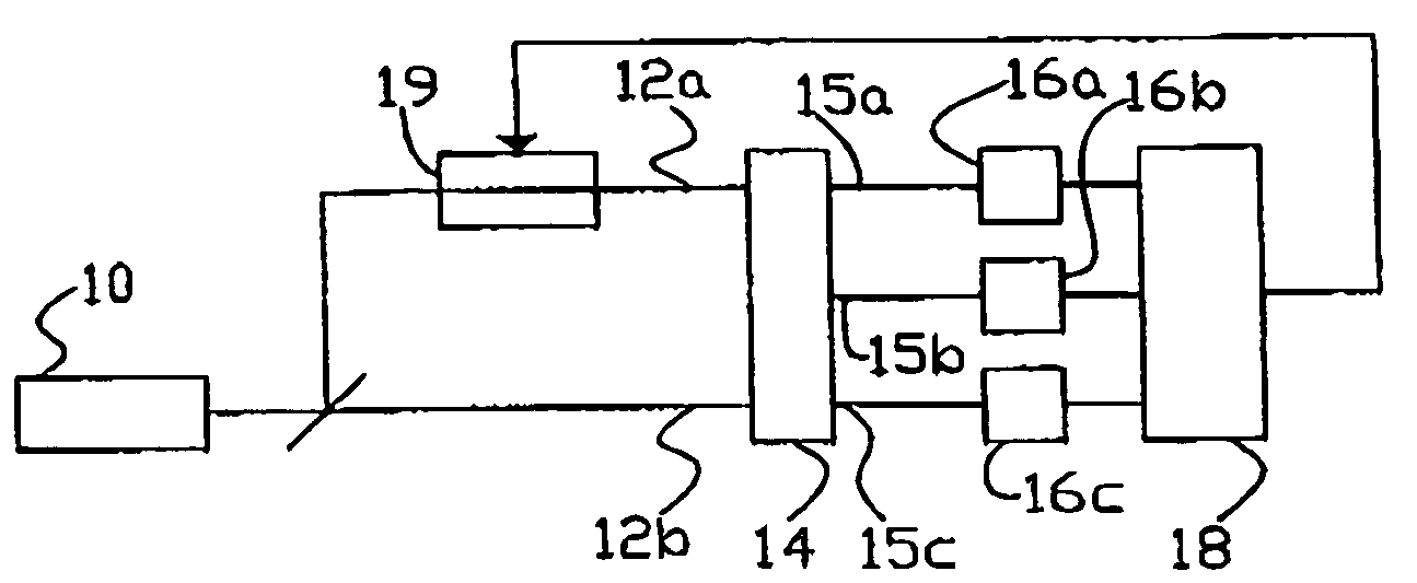
[0013]FIG. 1 shows an apparatus for measuring a path length difference. The apparatus comprises a light source 10, a coupler 14, detectors 16a-c, a oalculation unit 18 and a path length controller 19. Light from light source 10 is guided to a coupler 14 via two paths 12a,b. Light paths 12a,b each have their own path length, while the path lengths of the different light paths 12a,b can differ. Path length controller 19 is capable of adjusting the path length of one of the light paths under control. Further details of light paths 12a,b are not necessary to understand the invention and have therefore been omitted. Coupler 14 has three outputs which are each coupled to a respective detector 16a-c. Detectors 16a-c have outputs which are coupled to calculation unit 18. Calculation unit 18 has an output which is coupled to path length controller 19.

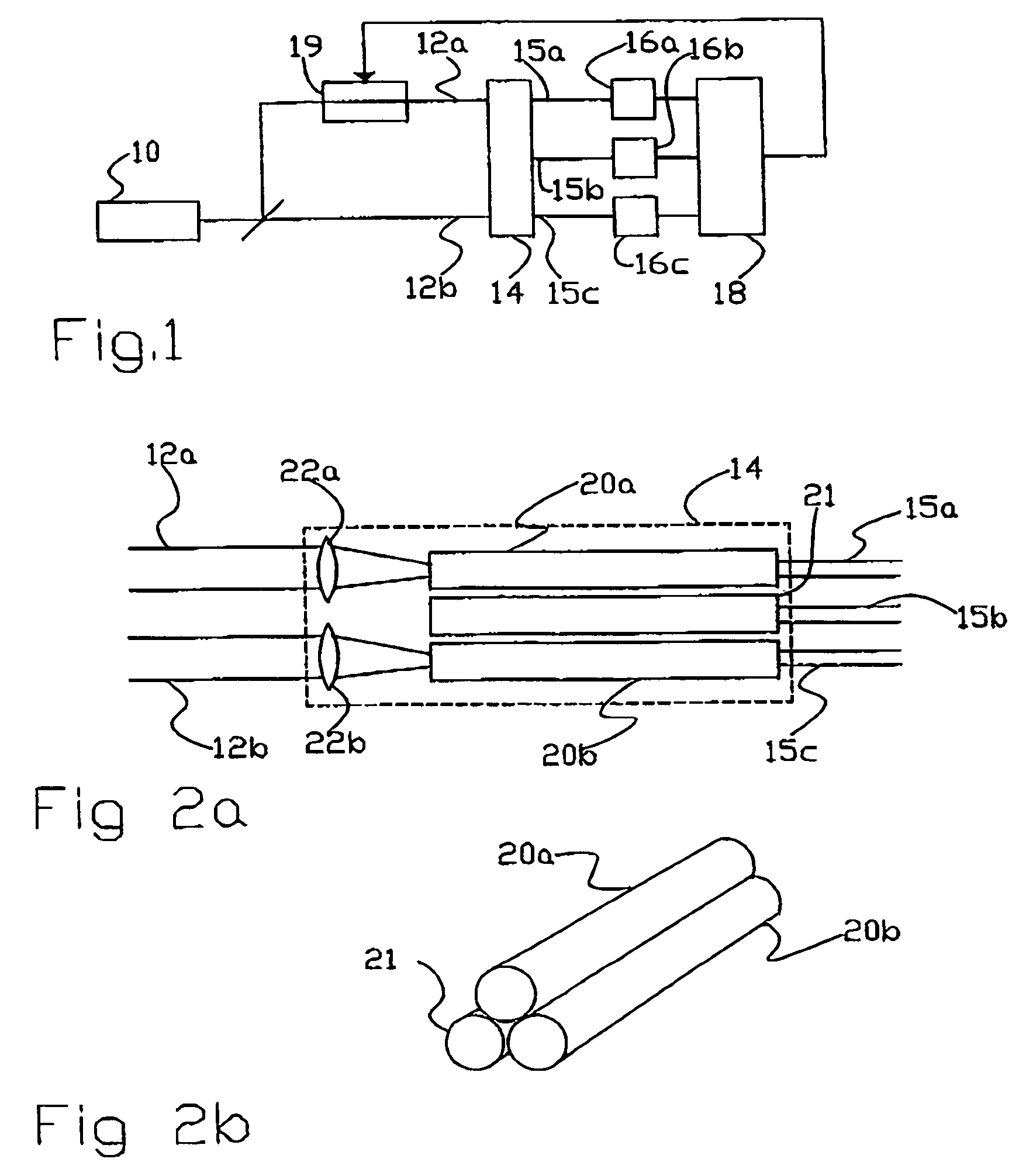
[0014]FIG. 2a shows an example of a three-way coupler 14. This embodiment of three-way coupler 14 contains three optical wave guides 20a,b, 21 ...


PUM


Abstract

In measuring an optical path length difference, light from a light source is guided through a first and a second path. A three-way coupler combines light from the first and the second path in at least three combination, with at least three mutually different added relative phase displacements. A detector measures interference intensities of the at least three combinations. From the intensities, a calculation unit determines a phase difference between the light from the first and second path while eliminating an effect of a contrast between the light from the first and second path.

Description

FIELD OF THE INVENTION[0001]The invention relates to an apparatus for measuring an optical path length difference, to a method for determining an optical path length difference and to a computer program product for use in such a method.BACKGROUND OF THE INVENTION[0002]Optical interference measurements make it possible to measure path length differences between different light paths with great accuracy. Here, light components which have first been guided through different paths are combined. The intensity of the combined light depends on the relative phase of the components which is caused by the path length difference. Thus, by measuring this intensity, information is obtained about the path length difference.[0003]Such measurements are often used in control systems in which the path length difference between the different paths has to be controlled out. When there is no path length difference, the intensity of a combination of the components in which the polarity of one of the comp...

Claims


Application Information

Patent Timeline
IPC IPC(8): G01B9/02G02B6/28
CPCG02B6/2821G01B9/02067G01B9/02083G02B2006/2865G01B2290/45
Inventor CHENG, LUN KAI
Owner NEDERLANDSE ORG VOOR TOEGEPAST-NATUURWETENSCHAPPELIJK ONDERZOEK (TNO)
Why Eureka
Try Eureka