Indexing dithering mechanism and method

Active Publication Date: 2008-10-16
EMCORE INC
View PDF10 Cites 4 Cited by
  • Summary
  • Abstract
  • Description
  • Claims
  • Application Information

AI Technical Summary

Benefits of technology

[0008]It is in general an object of the invention to provide a new and improved dither

Problems solved by technology

This non-zero output is called bias, and it can cause significant errors in inertial measurements.
However, bias is not fixed in time, and it tends to drift with changes such as temperature

Method used


Image

  • Indexing dithering mechanism and method
  • Indexing dithering mechanism and method
  • Indexing dithering mechanism and method

Examples


Embodiment Construction

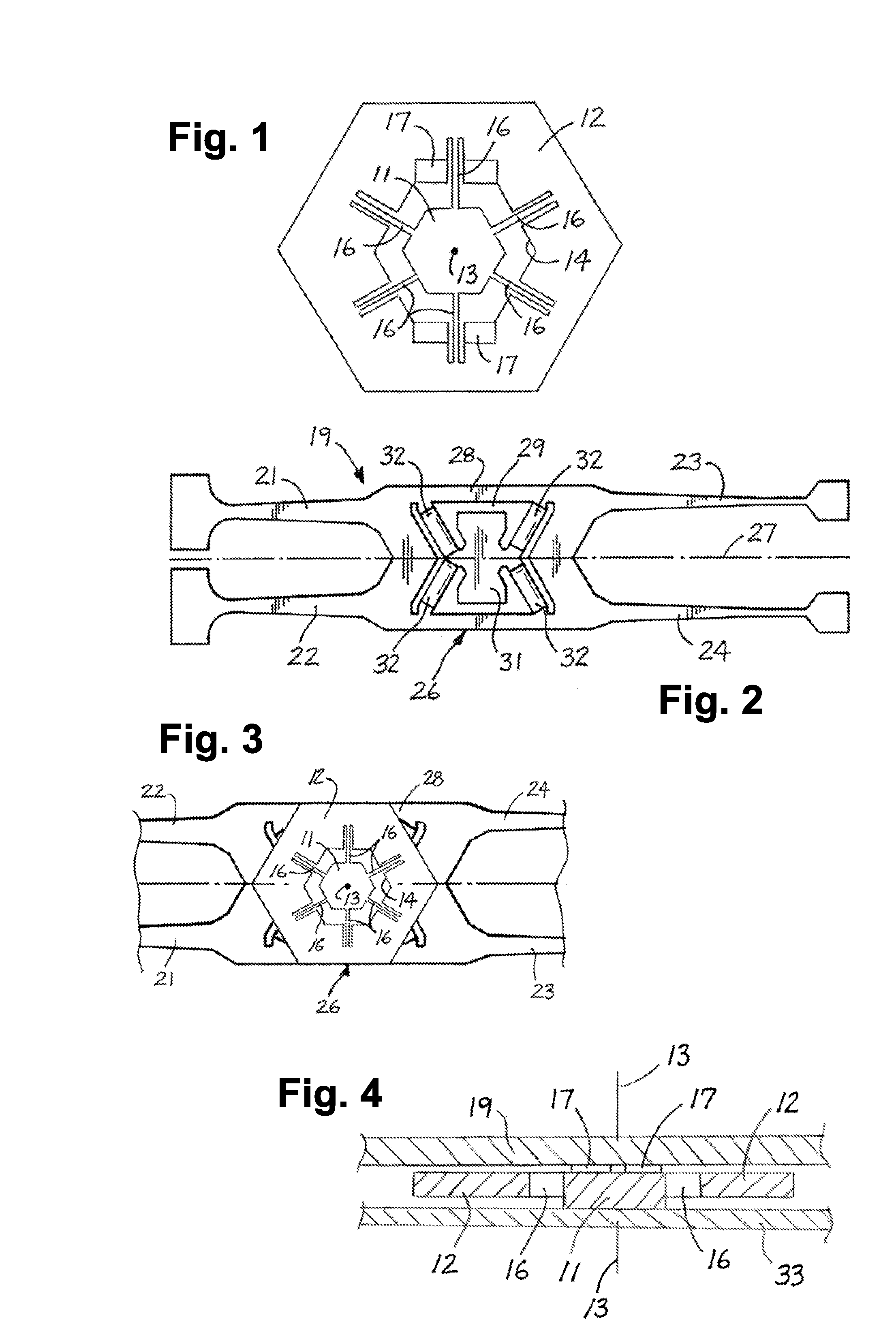
[0025]As illustrated in FIG. 1, the dithering mechanism includes a mounting post 11 and an outer ring 12 which is disposed coaxially about the post. Both the post and the ring are hexagonal in shape and centered about a dither axis 13, with the post in a hexagonal opening 14 in the ring. The ring is mounted to the post by radially extending flexure beams 16, and mounting pads 17 are provided on the upper side of the ring for attachment to the sensing element of a gyroscope.

[0026]The dithering mechanism is formed as a unitary structure of a piezoelectric material such as crystalline quartz and fabricated by micromachining techniques such as photo lithography, etching and surface deposition. The flexure beams are driven as piezoelectric actuators by signals applied to electrodes (not shown) mounted on the beams to dither the ring through a small angle, typically on the order of 10 degrees. In order to maintain a stable angle of dither, the drive signals preferably have an amplitude wh...


PUM


Abstract

Dithering mechanism and method for eliminating the effects of zero-rate bias in a rate sensor or gyroscope. Both continuously moving and indexing embodiments are disclosed. The mechanism includes a first part mounted in a fixed position centered about a dither axis perpendicular to the input axis of the gyroscope, a second part disposed coaxially of the first part and affixed to the sensing element of the gyroscope, and a plurality of piezoelectrically driven quartz flexure beams extending radially between the first and second parts for dithering the second part about the dither axis. In some embodiments, the dithering mechanism is formed separately from and affixed to the sensing element of the gyroscope, and in others it is formed integrally with the sensing element. In the indexing embodiments, radial arms and fixed stops limit movement of the mechanism between two fixed positions, and drive signals and holding potentials are applied alternately to dither the mechanism between the two positions and to hold it alternately in those positions during successive data acquisition periods.

Description

BACKGROUND OF THE INVENTION[0001]1. Field of Invention[0002]This invention pertains generally to angular rate sensors or gyroscopes and, more particularly, to a dithering mechanism and method for eliminating the effects of zero-rate bias in a rate sensor or gyroscope.[0003]2. Related Art[0004]Angular rate sensors or gyroscopes exhibit a non-zero output in the absence of rotation about the input axis. This non-zero output is called bias, and it can cause significant errors in inertial measurements. At the time of manufacture, the bias for each individual gyroscope can be measured and subtracted from the output to set the zero-rate output to zero. However, bias is not fixed in time, and it tends to drift with changes such as temperature and aging of the materials employed in the sensor. This may require periodic re-zeroing of a sensor in the field.[0005]Bias cancellation, or “washout”, mechanisms are employed in order to reduce or eliminate the effects of biases that slowly change wit...

Claims


Application Information

Patent Timeline
IPC IPC(8): H02N2/00
CPCG01C19/5621G01C19/5614G01C25/005
Inventor TCHERTKOV, IGOR LEONIDOVICHJAFFE, RANDALL
Owner EMCORE INC
Why Eureka
Try Eureka