
Chassis system and method for holding and protecting electronic modules

a chassis system and electronic module technology, applied in the direction of wave amplification devices, electrical equipment, support structure mounting, etc., can solve the problems of increasing the electronic modules are typically not designed to survive in harsh environments, and the risk of electronic modules failing to work

Inactive Publication Date: 2013-12-12
THE BOEING CO
View PDF21 Cites 51 Cited by
  • Summary
  • Abstract
  • Description
  • Claims
  • Application Information

AI Technical Summary

Benefits of technology

The patent describes a chassis system that includes a body, a lid, a cavity, a backplane, and an electrically conductive connector. The lid is attached to the body, creating a cavity that is completely enclosed. The system also includes a plurality of thermally conductive rails and an electronic module in contact with the backplane. The chassis system can be wired or wireless, allowing for the flow of electricity or data between the connector and the backplane. The patent also includes a method of manufacturing the chassis system. The technical effects include an enclosed cavity that prevents the entry of electromagnetic waves, and a backplane that allows for secure attachment and communication with an electronic module. The system also provides a more efficient cooling mechanism for electronic components.

Problems solved by technology

Electronic modules, such as commercial off the shelf modules, are typically not designed to survive in harsh environments such as in military or civilian aviation environments, or in other types of harsh environments.
Integrating these electronic modules into a standard chassis does not reduce their environmental exposure and increases the risk that the electronic modules will fail.

Method used


Image

  • Chassis system and method for holding and protecting electronic modules
  • Chassis system and method for holding and protecting electronic modules
  • Chassis system and method for holding and protecting electronic modules

Examples


Embodiment Construction

[0015]The following detailed description is of the best currently contemplated modes of carrying out the disclosure. The description is not to be taken in a limiting sense, but is made merely for the purpose of illustrating the general principles of the disclosure, since the scope of the disclosure is best defined by the appended claims.

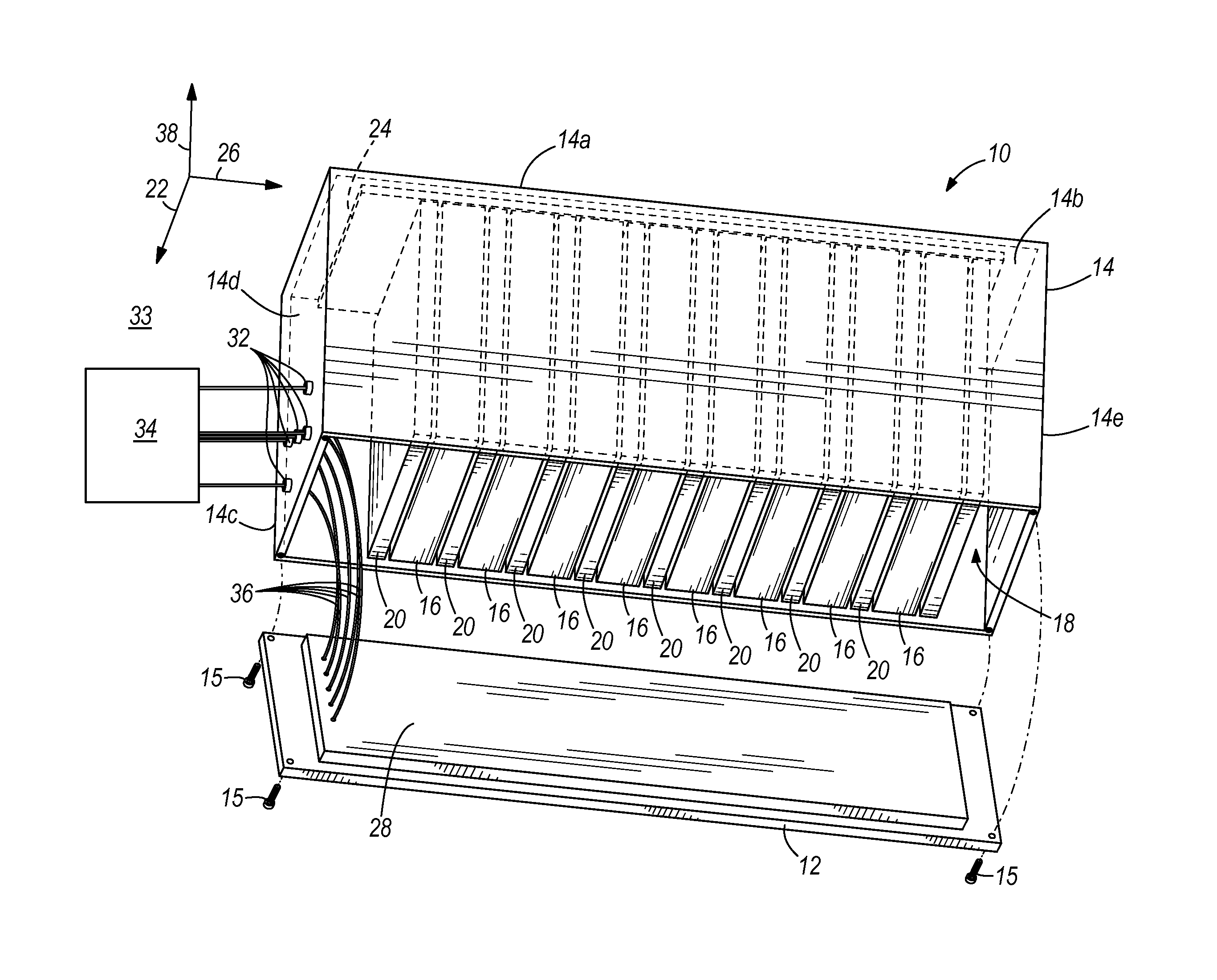
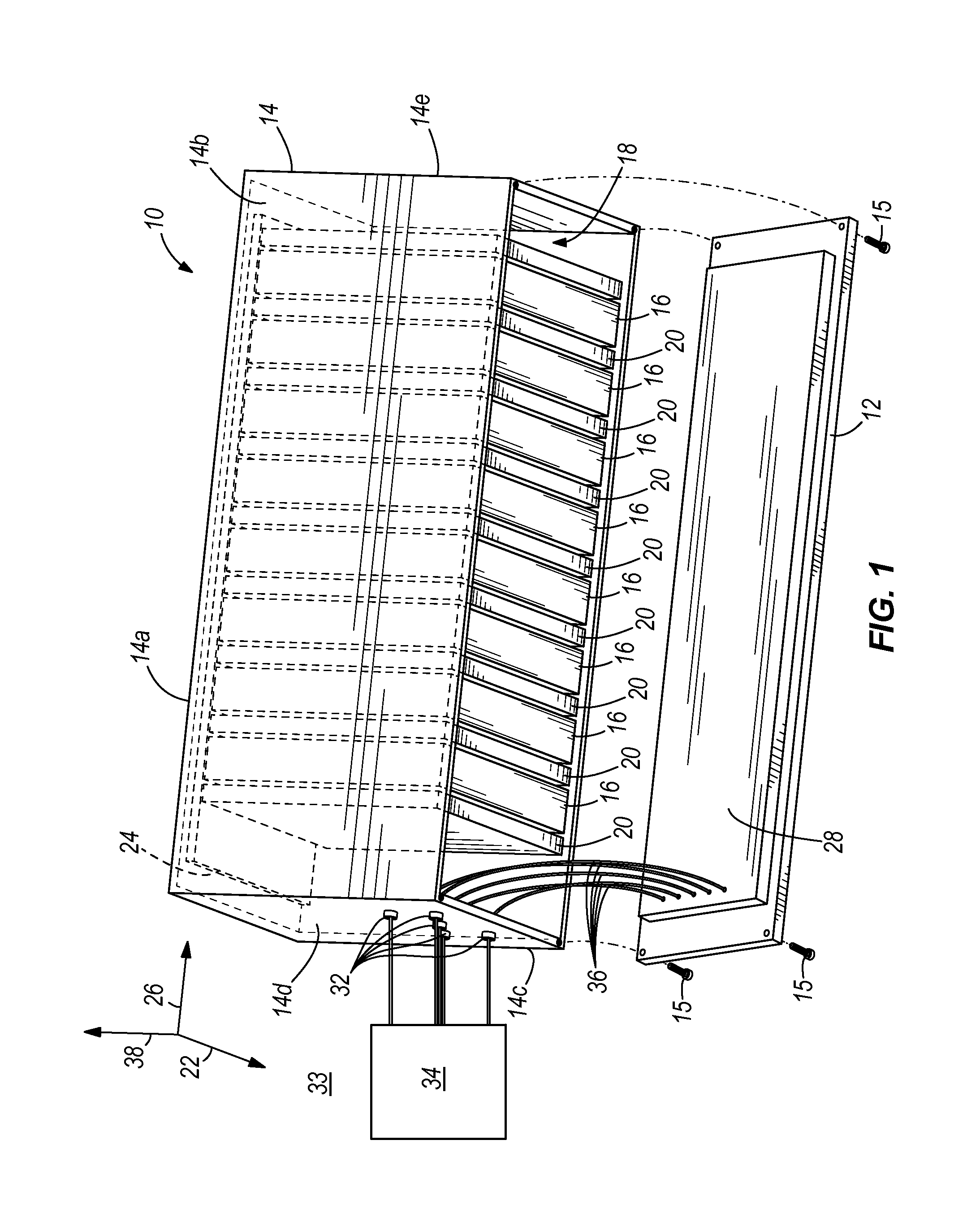
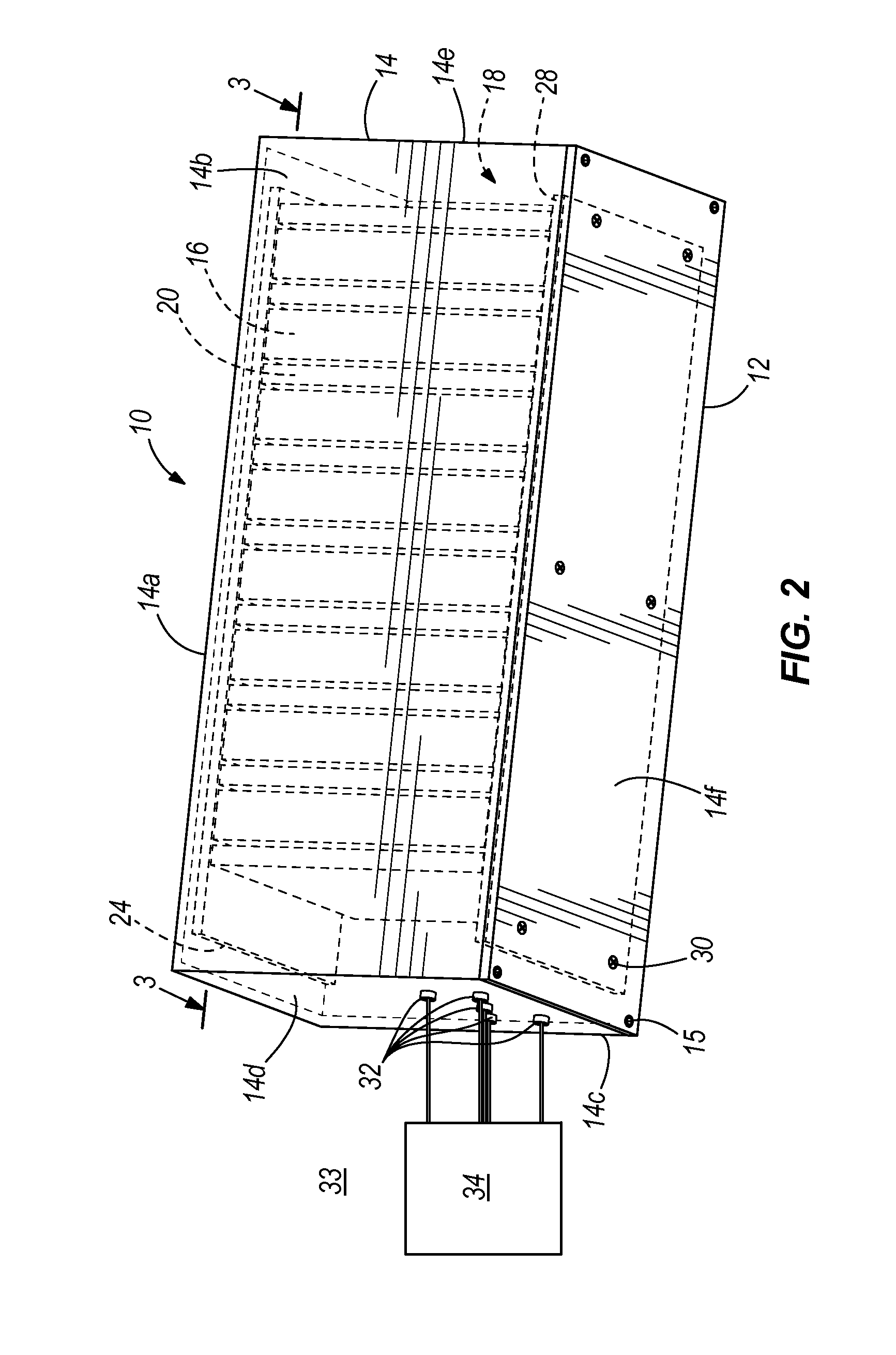
[0016]FIG. 1 illustrates a bottom perspective view of one embodiment of a chassis system 10 with a lid 12 removed from a body 14 exposing electronic modules 16 held within a cavity 18 of the body 14. FIG. 2 illustrates a bottom perspective view of the chassis system 10 of FIG. 1 with the lid 12 attached to the body 14 securing the electronic modules 16 within the cavity 18 of the body 14. FIG. 3 illustrates a cross-section view through line 3-3 in the chassis system 10 of FIG. 2. FIG. 4 illustrates a side-view of the chassis system 10 of FIG. 2 with metamaterial isolators 19 attached to the lid 12 and disposed against a structure 21.

[0017]As shown in...


PUM


Abstract

A chassis system includes a body, a lid, a cavity, a backplane, and an electrically conductive connector. The lid is removably attached to the body such that when the lid is attached to the body a cavity within the body is completely enclosed by the body and the attached lid. The lid and the body are made of at least one material that does not allow electromagnetic waves to enter the cavity. The backplane is attached to the body or the lid. The electrically conductive connector is attached to the body or lid. The connector is in wired or wireless communication with the backplane for allowing electricity or data to flow between the electrically conductive connector and the backplane. The chassis system may be used to environmentally protect one or more electronic modules inserted into the cavity of the chassis system.

Description

FIELD OF THE DISCLOSURE[0001]The disclosure relates to systems and methods for holding or protecting electronic modules from environmental conditions.BACKGROUND OF THE DISCLOSURE[0002]Electronic modules, such as commercial off the shelf modules, are typically not designed to survive in harsh environments such as in military or civilian aviation environments, or in other types of harsh environments. Integrating these electronic modules into a standard chassis does not reduce their environmental exposure and increases the risk that the electronic modules will fail.[0003]There is a need for a chassis system and method which will protect electronic modules from harsh environments.SUMMARY OF THE DISCLOSURE[0004]In one embodiment, a chassis system includes a body, a lid, a cavity, a backplane, and an electrically conductive connector. The lid is removably attached to the body such that when the lid is attached to the body a cavity within the body is completely enclosed by the body and the...

Claims


Application Information

Patent Timeline
Patent Type & Authority Applications(United States)
IPC IPC(8): H05K7/16H05K13/00
CPCH05K7/20445H05K9/0047Y10T29/49002
Inventor WILKINS, DONALD FRANK
Owner THE BOEING CO
Learn More