

Central compressor variable refrigerant flow air conditioning sysytem
a technology of air conditioning and compressor, which is applied in the direction of refrigeration components, lighting and heating apparatus, heating types, etc., can solve the problems of limited prior art refrigerant piping lengths and severe curtailment of prior art applications
- Summary
- Abstract
- Description
- Claims
- Application Information
AI Technical Summary
Benefits of technology
Problems solved by technology
Method used
Image

Examples
Embodiment Construction
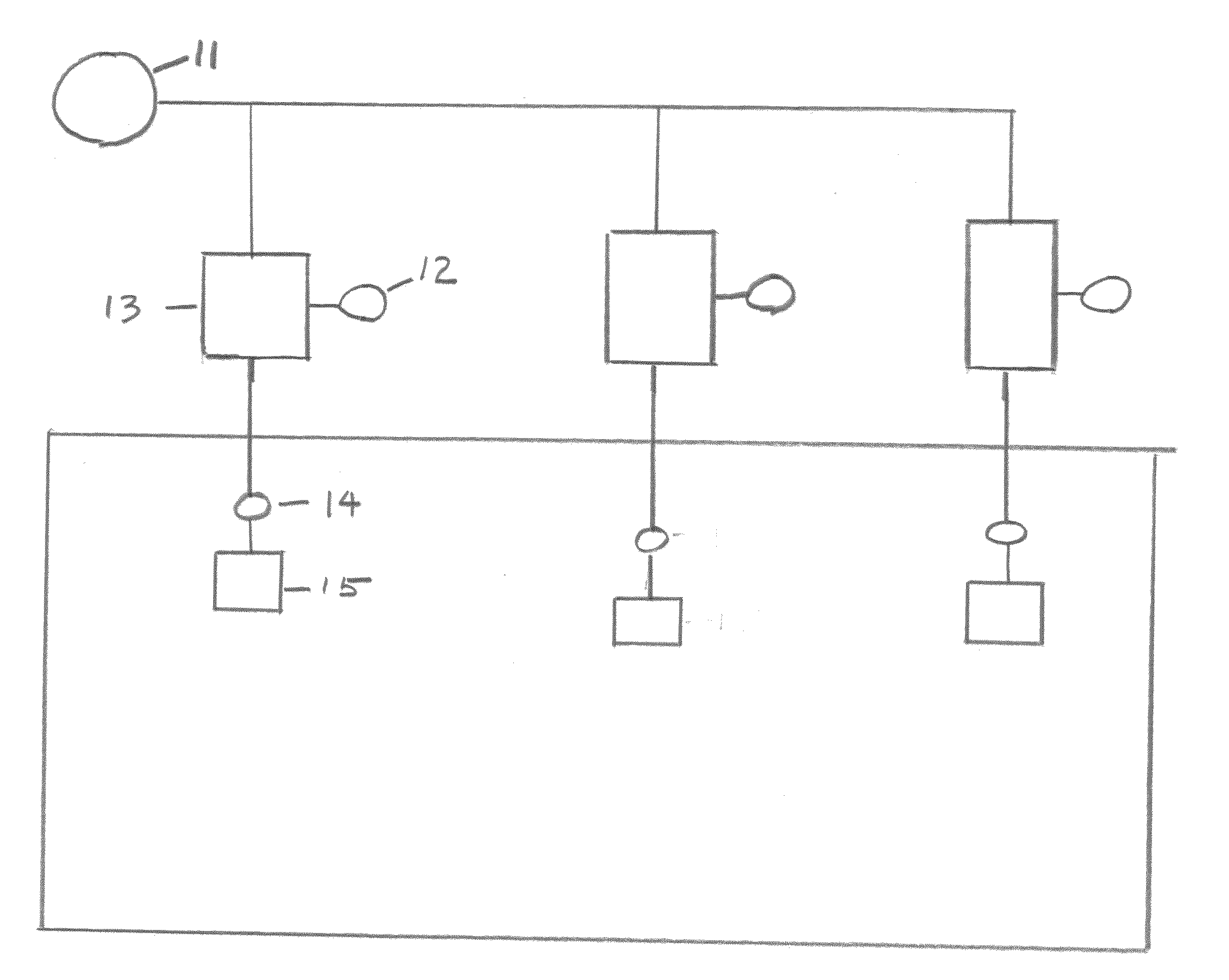
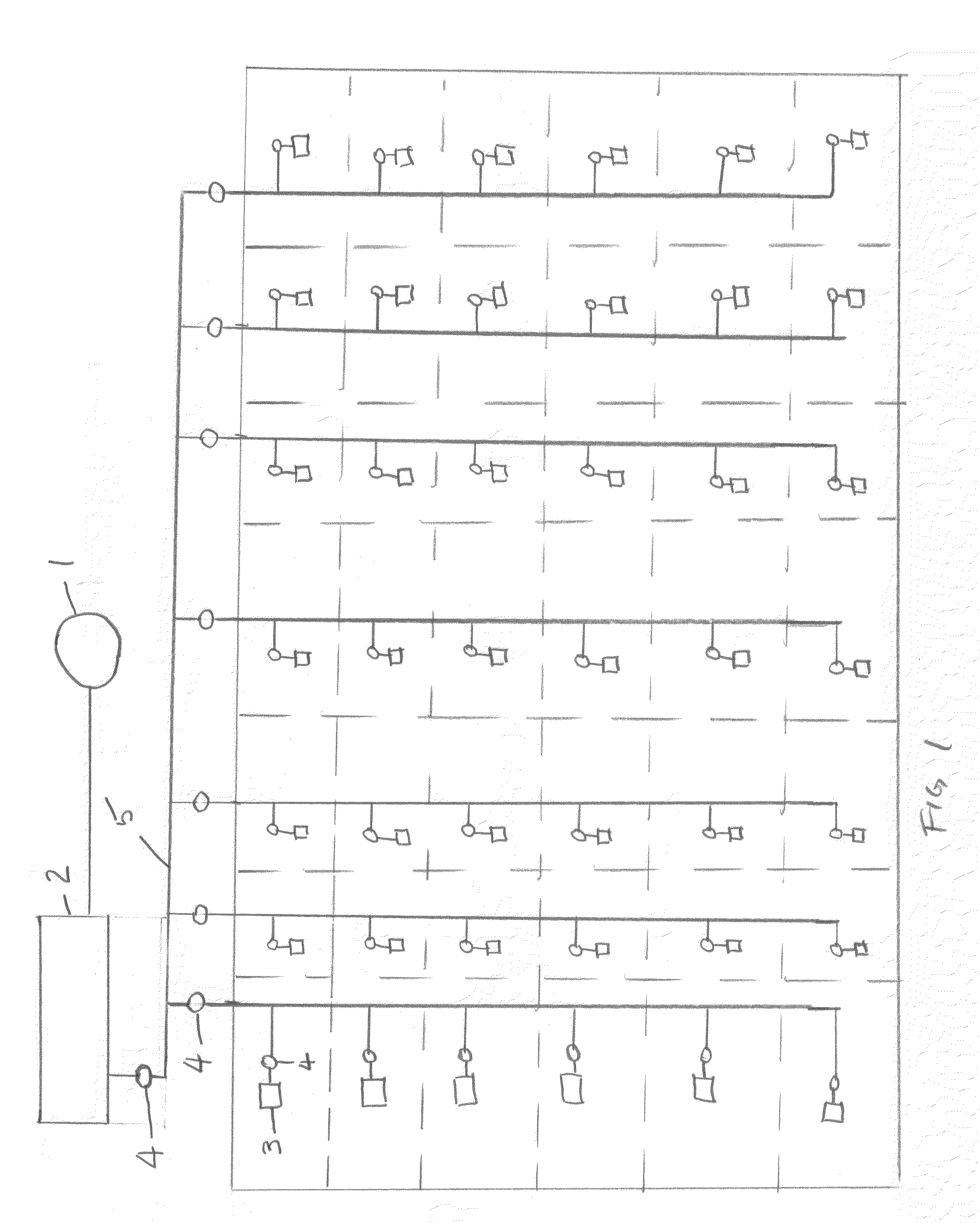
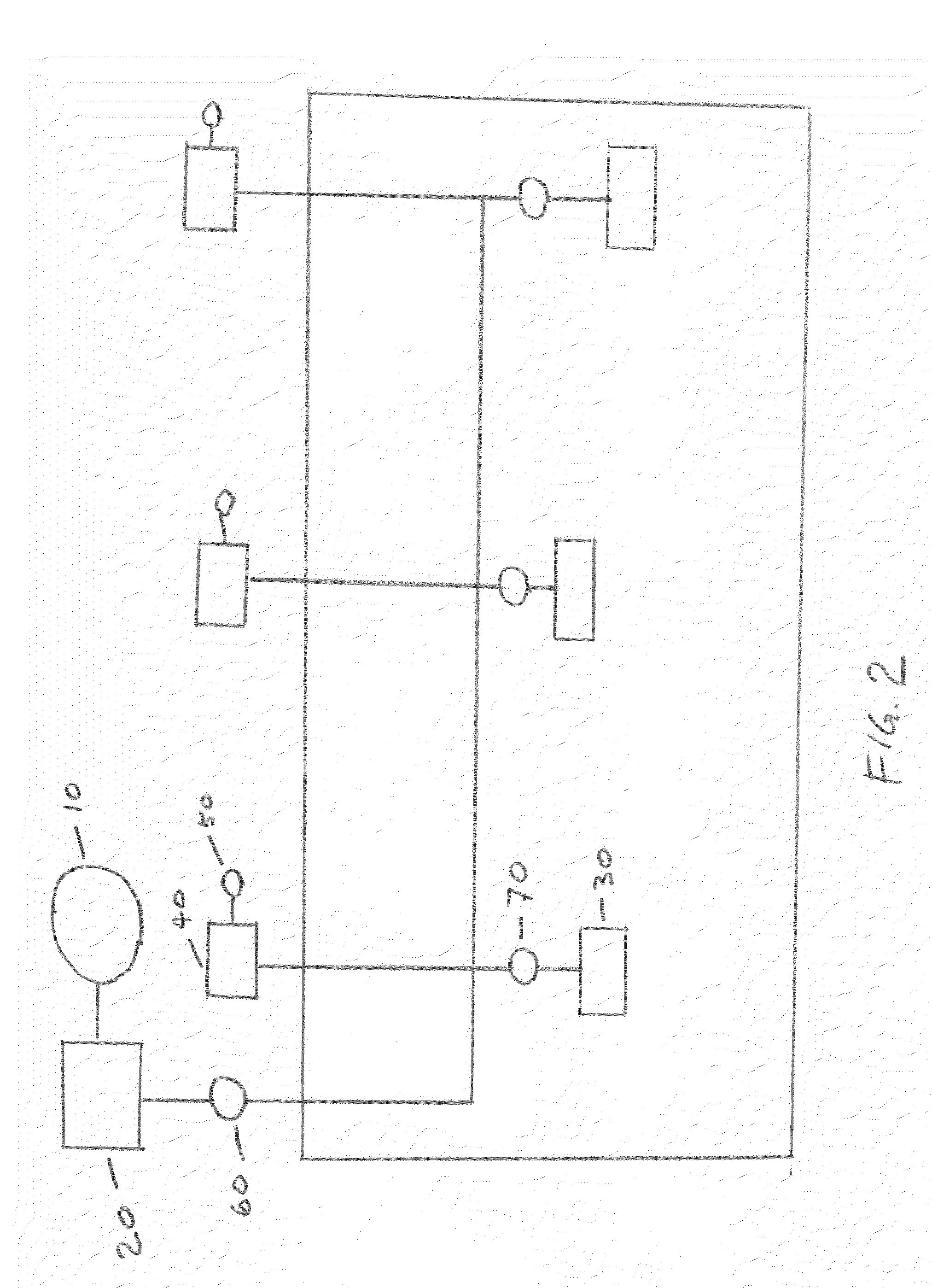
[0023]FIG. 1 sets out an overall schematic view of the present application. Central station compressor 1 consists of magnetic levitation bearing types requiring no entrained oil in the refrigerant fluid. It compresses the oil free refrigerant and delivers it to a central condenser package 2 for removal of heat from the refrigerant. Thereafter the refrigerant travels to the various evaporators 3 which are placed in the building space at locations where heat is to be removed from the space.
[0024]Expansion valves 4 are disposed at appropriate locations upstream of the various evaporators 3.
[0025]By controlling the refrigerant flow to each evaporator 3, using an electronic control / flow control system (not shown), the amount of cooling can be carefully and specifically regulated at each cooling location.
[0026]By virtue of the present invention, the distances in the spans of the refrigerant piping are no longer limited in particular due to the absence of entrained oil in the refrigerant l...
PUM
 Abstract
Description
Claims
Application Information