Reactor in deposition device with multi-staged purging structure

a technology of purging structure and deposition device, which is applied in chemical vapor deposition coating, metal material coating process, coating, etc., can solve the problems of undesirable characteristics of the layer, and achieve the effect of facilitating the removal of excess material remaining

Inactive Publication Date: 2013-12-19
VEECO ALD
View PDF3 Cites 171 Cited by
  • Summary
  • Abstract
  • Description
  • Claims
  • Application Information

AI Technical Summary

Benefits of technology

[0009]Embodiments relate to a reactor formed with multiple constriction zones that facilitate removal of excess material remaining on a substrate. The reactor is formed with a first chamber, a second chamber, a first constriction zone, a second constriction zone and an exhaust portion. The first chamber injects a first gas onto the substrate passing across the first chamber. The second chamber injects a second gas onto the substrate passing across the second chamber. The first constriction zone is configured to route the first gas from the first chamber to the second chamber over the substrate. The first constriction zone is formed between the first chamber and the second chamber. The first constriction zone is configured so that th

Problems solved by technology

If excess precursors or other materials remain on the substrate after the

Method used


Image

  • Reactor in deposition device with multi-staged purging structure
  • Reactor in deposition device with multi-staged purging structure
  • Reactor in deposition device with multi-staged purging structure

Examples


Embodiment Construction

[0030]Embodiments are described herein with reference to the accompanying drawings. Principles disclosed herein may, however, be embodied in many different forms and should not be construed as being limited to the embodiments set forth herein. In the description, details of well-known features and techniques may be omitted to avoid unnecessarily obscuring the features of the embodiments.

[0031]In the drawings, like reference numerals in the drawings denote like elements. The shape, size and regions, and the like, of the drawing may be exaggerated for clarity.

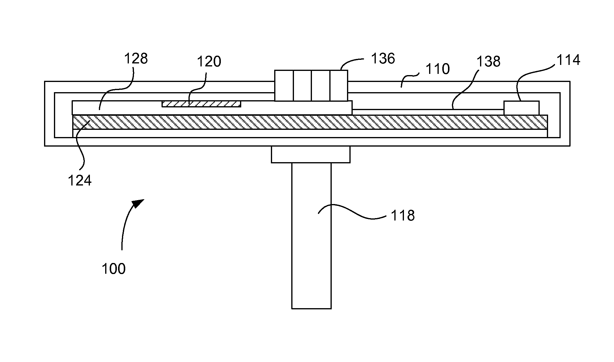
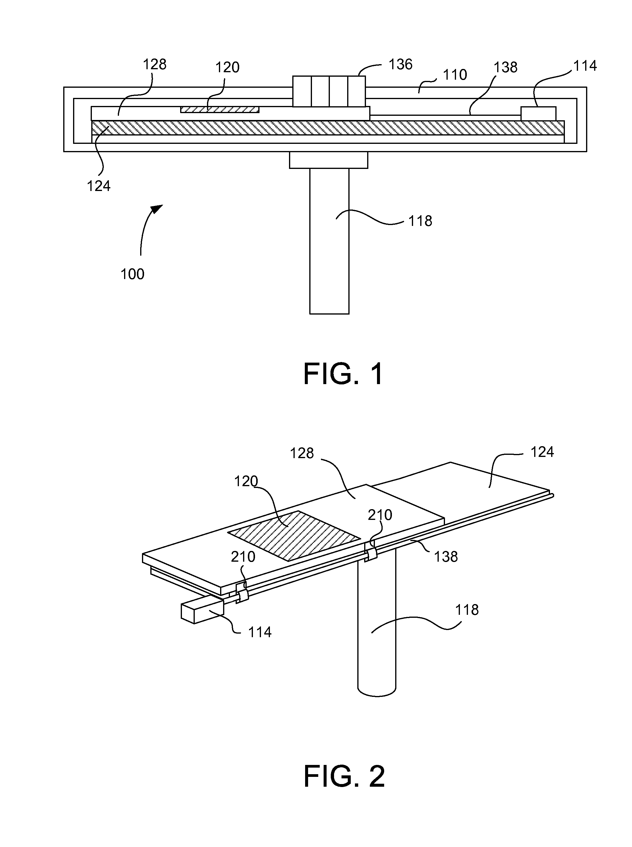
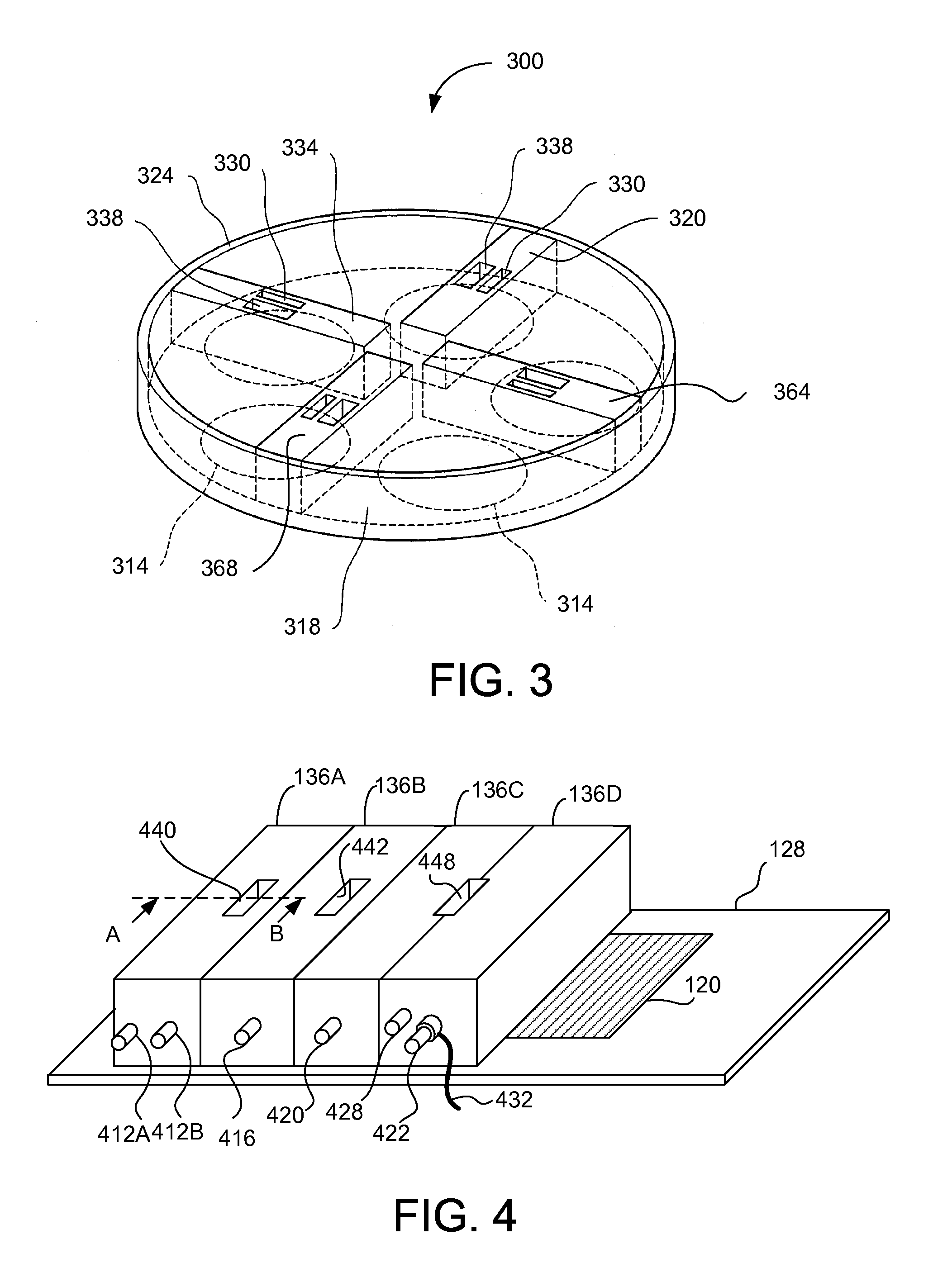
[0032]Embodiments relate to a structure of reactors in a deposition device that enables efficient removal of excess material (e.g., physisorbed precursor molecules) deposited on a substrate by using multiple constructions zones to cause multiple-staged Venturi effect. In a reactor, constriction zones of different heights are formed between injection chambers and an exhaust portion. As purge gas or precursor travels from injection...


PUM

PropertyMeasurementUnit
Pressureaaaaaaaaaa
Speedaaaaaaaaaa
Heightaaaaaaaaaa

Abstract

Embodiments relate to a structure of reactors in a deposition device that enables efficient removal of excess material deposited on a substrate by using multiple-staged Venturi effect. In a reactor, constriction zones of different height are formed between injection chambers and an exhaust portion. As purge gas or precursor travels from injection chambers to the exhaust portion and passes the constriction zones, the pressure of the gas drops and the speed of the gas increase. Such changes in the pressure and speed facilitate removal of excess material deposited on the substrate.

Description

CROSS-REFERENCE TO RELATED APPLICATION[0001]This application claims priority under 35 U.S.C. §119(e) to co-pending U.S. Provisional Patent Application No. 61 / 661,750, filed on Jun. 19, 2012, which is incorporated by reference herein in its entirety.BACKGROUND[0002]1. Field of Art[0003]The disclosure relates to depositing one or more layers of materials on a substrate by using atomic layer deposition (ALD) or other deposition methods, and more particularly to effectively removing excess material from the substrate.[0004]2. Description of the Related Art[0005]Various chemical processes are used to deposit one or more layers of material on a substrate. Such chemical processes include, among others, chemical vapor deposition (CVD), atomic layer deposition (ALD) and molecular layer deposition (MLD). CVD is the most common method for depositing a layer of material on a substrate. In CVD, reactive gas precursors are mixed and then delivered to a reaction chamber where a layer of material i...

Claims


Application Information

Patent Timeline
IPC IPC(8): C23C16/455
CPCC23C16/455C23C16/45551C23C16/44C23C16/448
Inventor LEE, SANG IN
Owner VEECO ALD
Why Eureka
Try Eureka