Shoulder base plate coverage and stability

Inactive Publication Date: 2013-12-19
MATERIALISE NV
View PDF7 Cites 143 Cited by
  • Summary
  • Abstract
  • Description
  • Claims
  • Application Information

AI Technical Summary

Benefits of technology

[0010]Accordingly, a method has been developed which allows the identification of the surface combinati

Problems solved by technology

However, based on these features alone, the stability of the patient-specific device is relatively unknown.
This is a very inefficient method because the number of surface combinations that need to be assessed is high and the patient-specific devices, or at least a part thereof, need to be physically produced before the stability can be analyzed.
Furthermore, the stability of these devices

Method used


Image

  • Shoulder base plate coverage and stability
  • Shoulder base plate coverage and stability
  • Shoulder base plate coverage and stability

Examples


examples

[0122]The following examples relate to patient-specific instruments for shoulder surgery.

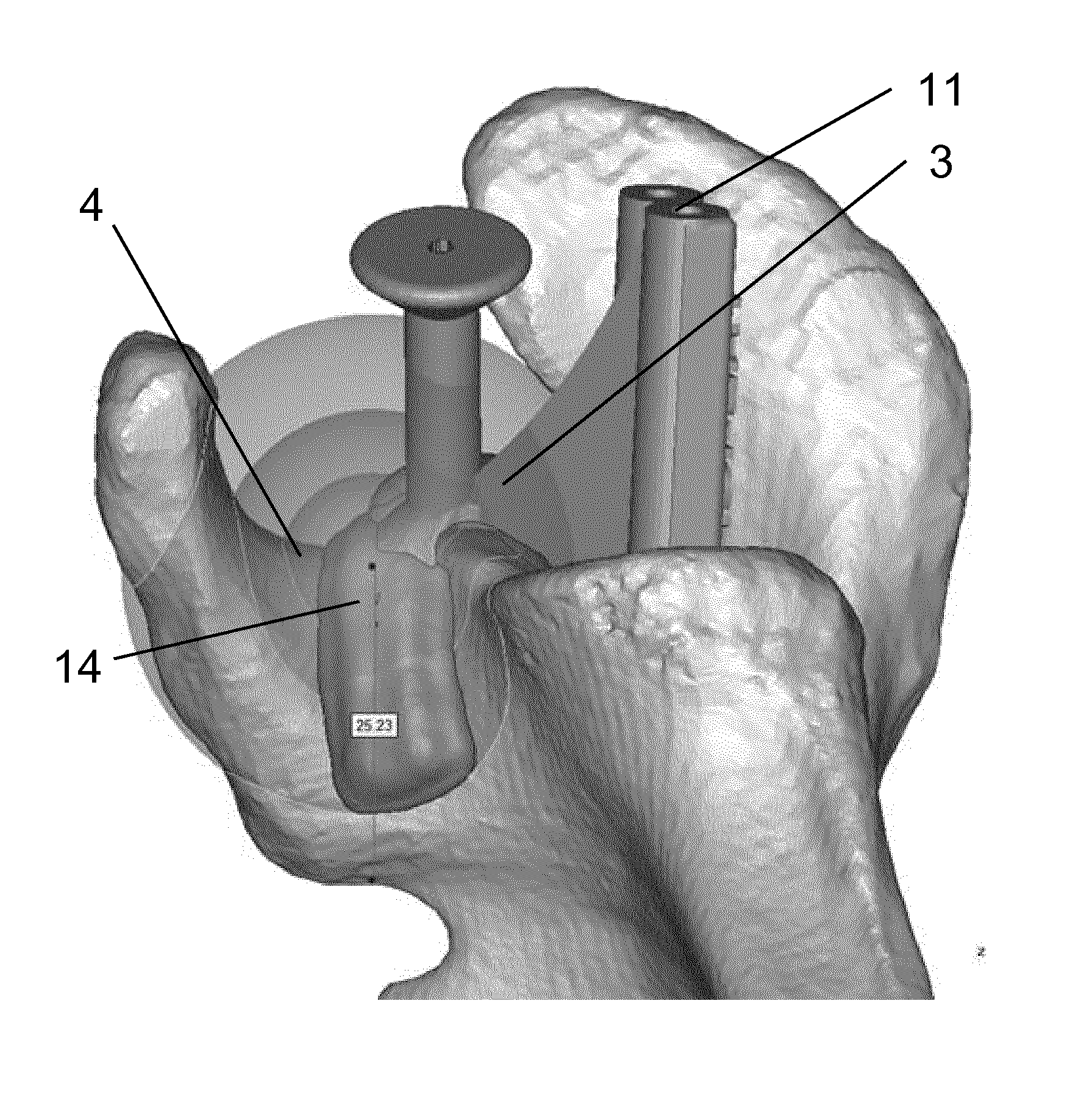
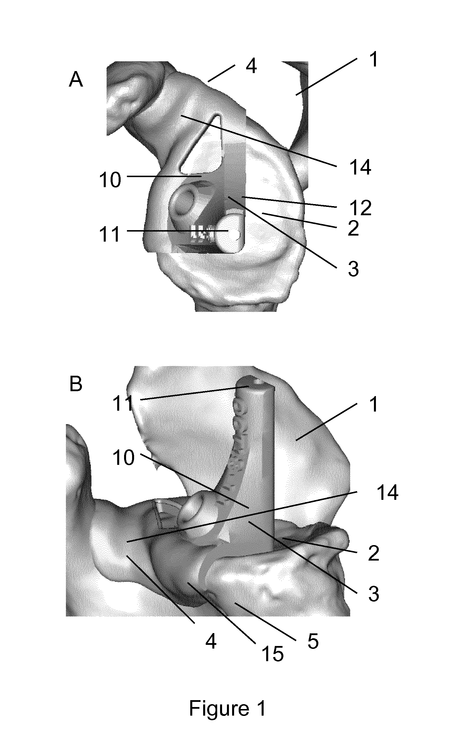
[0123]FIG. 1 illustrates a patient-specific surgical guide positioned on the glenoid. FIGS. 1 A and B illustrate a shoulder joint (1) with particular anatomical features including the glenoid (2), the neck of the coracoid process (4) and the anterior surface of the glenoid (5). Onto the shoulder joint (1) a patient-specific surgical guide (3) is positioned. The patient-specific surgical guide (3) comprises a support structure (10), a guiding feature (11) and several patient-specific contact elements including a contact element at least partially complementary to the surface of the glenoid face (12), a contact element at least partially complementary to the neck of the coracoid process (14) and a contact element at least partially complementary to the anterior surface of the glenoid (15).

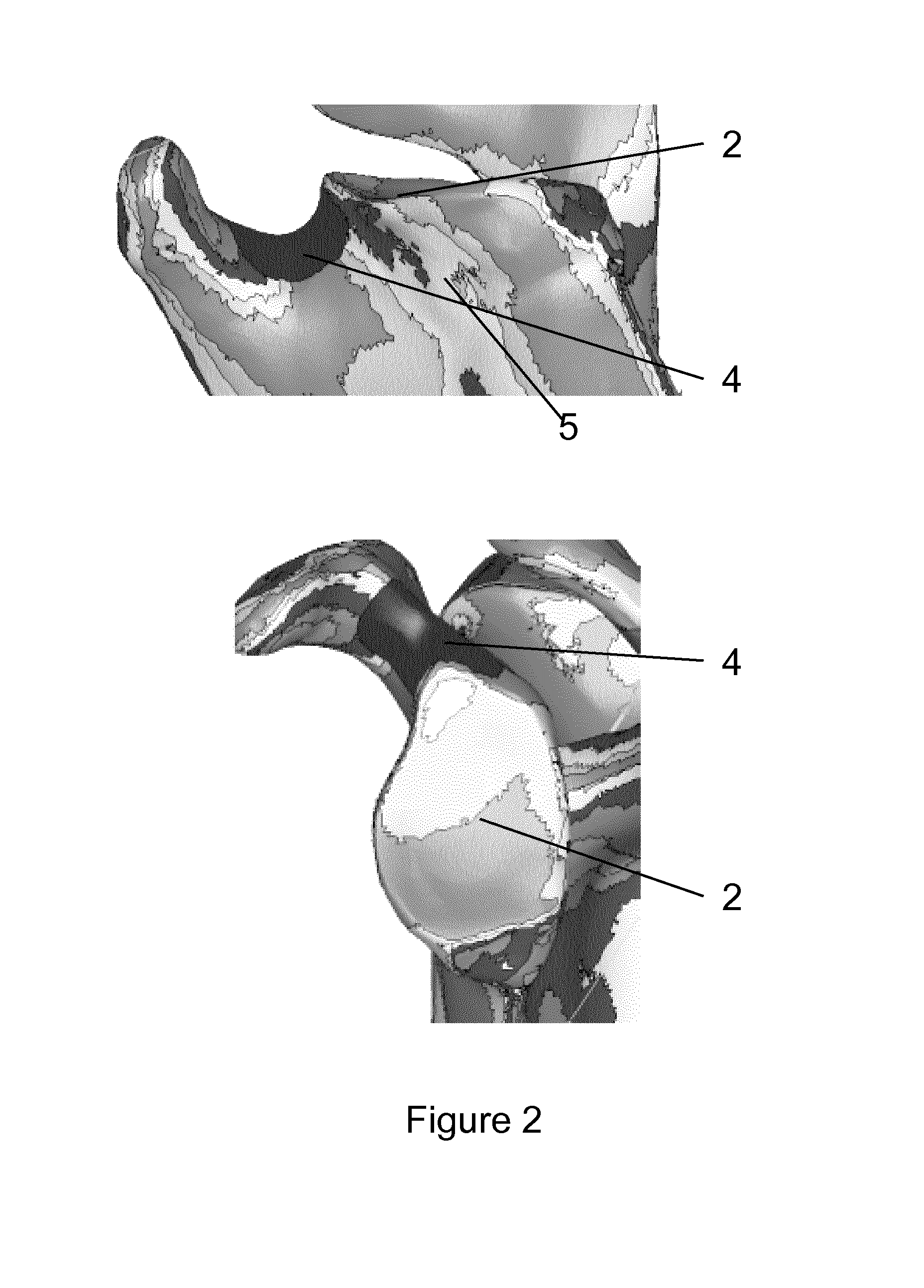
[0124]FIG. 2 illustrates a shoulder joint (1) with particular anatomical features including the glenoid (2), t...


PUM

PropertyMeasurementUnit
Angleaaaaaaaaaa
Structureaaaaaaaaaa
Distanceaaaaaaaaaa

Abstract

Provided herein are patient-specific surgical device that allow for a stable fitted position for use in shoulder surgery. The patient-specific surgical devices may have different functions such as a function as a guide.

Description

FIELD OF THE INVENTION[0001]Provided herein are patient-specific surgical devices that provide a stable fitted position for use in shoulder surgery, fitting within a typical surgical incision. The patient-specific surgical devices may be used for various purposes including for use as or with a shoulder guide.BACKGROUND[0002]Conventional orthopedic prostheses, guides and implants have been in use for many years with considerable success. The use of custom designed prostheses, guides and implant components based on the patient-specific anatomy has moreover overcome many shortcomings of the older designs. Such patient-specific devices can be developed using commercially available software. Typically such devices are used for orthopedic interventions to the spine, hip, shoulder, knee and / or radius. Patient-specific devices available on the market include patient-specific knee replacement prostheses, patient-specific femoral and tibia cutting blocks, distal radius drilling, cutting templ...

Claims


Application Information

Patent Timeline
IPC IPC(8): A61B17/17A61B17/88
CPCA61B17/1739A61B2017/568Y10T29/49A61B17/8872Y10T29/49771A61B2019/508A61B2034/108A61B17/1778B33Y80/00
Inventor KEPPLER, LOUIS
Owner MATERIALISE NV
Why Eureka
Try Eureka