Force sensor including sensor plate with local differences in stiffness

a sensor and local difference technology, applied in the field of force sensors, can solve problems such as affecting the measuring sensitivity of said known force sensors

Inactive Publication Date: 2013-12-26
TECSIS
View PDF13 Cites 29 Cited by
  • Summary
  • Abstract
  • Description
  • Claims
  • Application Information

AI Technical Summary

Benefits of technology

[0022]If plural measuring resistors are used, especially when plural measuring resistors on different portions of the sensor plate are used, not only a pair of forces/counter-forces vertical with respect to the plate can be measured, but also the direction of force and the place of force application related to the center of the s

Problems solved by technology

The known arrangement has the drawback, however, that for a reasonable practical application a minimum stability of the plate-shaped

Method used


Image

  • Force sensor including sensor plate with local differences in stiffness
  • Force sensor including sensor plate with local differences in stiffness
  • Force sensor including sensor plate with local differences in stiffness

Examples


Embodiment Construction

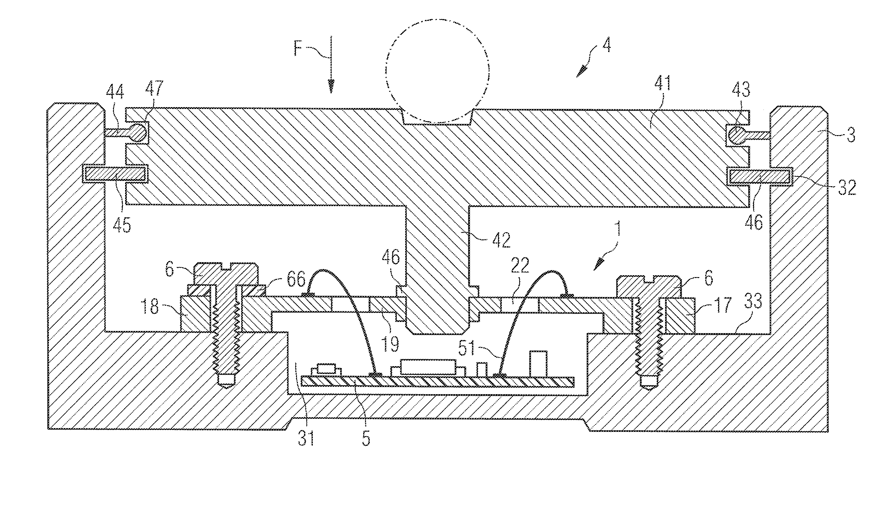
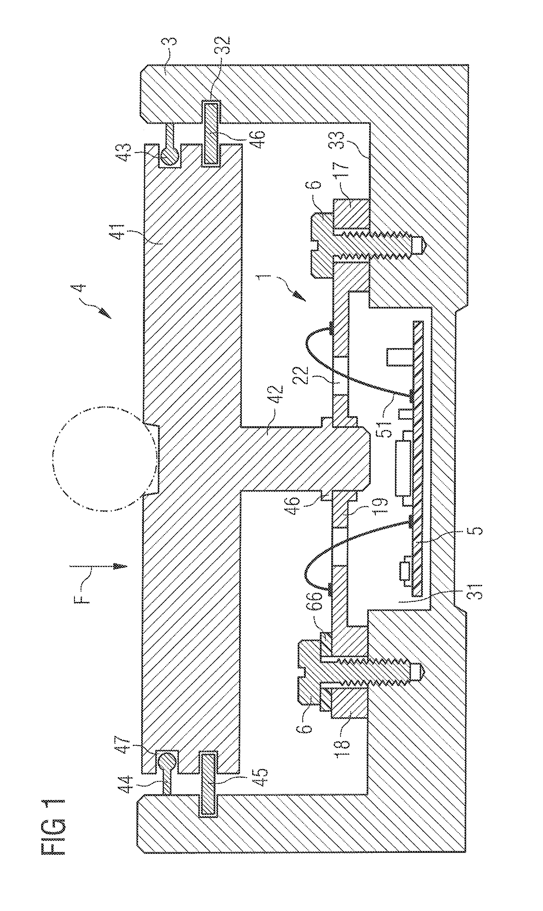
[0040]FIG. 1 shows a first embodiment for a force sensor in a sectional view. The force sensor shown in FIG. 1 has a cup-shaped housing 3 receiving a sensor plate 1 as well as a coupling member 4 in its interior. At the inner circumference of the wall portion of the cup-shaped housing 3 a circumferential groove 32 is formed into which a ring 45 engaging in a circumferential groove 46 of the coupling member 4 can be inserted. Both the groove 32 and the circumferential groove 46 are provided with sufficient play so that the coupling member 4 can move in a downward direction in FIG. 1. The inserted ring 45 serves as stop element preventing destruction of a sensor plate 1 coupled to the coupling member 4. The coupling member 4 includes a circumferential groove 47 formed above the circumferential groove 46 in which a seal 43 is accommodated. The seal 43 is made of an elastomer and includes a sealing lip 44 projecting in the circumferential direction which is in sealing contact with the w...


PUM


Abstract

A force sensor for measuring forces comprises a sensor plate where at least one measuring resistor is arranged whereby deformations of the sensor plate can be detected as a result of forces to be measured. The sensor plate includes at least one local weakened area whereby deformation behavior of the sensor plate is influenced. The weakened area results in bypassing the flux of force in the sensor plate and in concentrating the forces at non-weakened portions of the sensor plate. The at least one measuring resistor is preferably arranged at such non-weakened deforming portion of the sensor plate. The at least one weakened area defines sensor plate portions separated from at least in sections, the sensor plate portions being exposed to opposite forces. The sensor plate can be mounted in a housing with an evaluation circuit, for example, and constitute a force sensor having compact dimensions and high measuring sensitivity.

Description

CROSS-REFERENCE TO RELATED APPLICATION[0001]This application claims priority to foreign German patent application No. DE 102012210021.0, filed on Jun. 14, 2012, the disclosure of which is incorporated by reference in its entirety.FIELD OF THE INVENTION[0002]The invention relates to a force sensor for measuring forces, wherein the force sensor makes use of a sensor plate on which at least one measuring resistor is arranged. The sensor plate is slightly deformed by the applied forces to be measured and the deformation of the sensor plate influences the value of the measuring resistor. Thus the magnitude and the direction of the forces acting on the sensor plate can be concluded from the value of the measuring resistor so that a force sensor is obtained in this way.[0003]Preferably plural measuring resistors are arranged on a sensor plate, wherein a bridge circuit is used to accurately measure the resistance values of the measuring resistors. Preferably the forces can be concluded from...

Claims


Application Information

Patent Timeline
IPC IPC(8): G01L1/22
CPCG01L1/2287G01L5/161
Inventor FREIWALD, FLORIANJOST, OLIVERMULLER, MARKUS
Owner TECSIS
Why Eureka
Try Eureka