Compound holding device for retaining tools

Inactive Publication Date: 2014-01-02
ZAPPIA LORENZO
View PDF29 Cites 0 Cited by
  • Summary
  • Abstract
  • Description
  • Claims
  • Application Information

AI Technical Summary

Benefits of technology

The invention is an improved compound holding device like a hawk or pan used in drywall or masonry applications. It solves problems of previous devices by making it easier to access various tools and devices used in these applications. The hawk has a plate with a handle and a cushion ring for added comfort. The plate also has magnets on its bottom surface that can hold ferromagnetic tools and devices. This allows workers to conveniently keep tools on the hawk and use them repeatedly without them falling. The technical effects of the invention include increased efficiency and convenience for workers.

Problems solved by technology

Workers have to handle a number of tools keeping them in different places such as their pockets, work belts, benches and the floor, and the time spent switching between tools is considerable.
Further, when on a scaffold or other elevated location, dropping a tool results in the worker having to descend and retrieve the tool before ascending to continue work.
Further, the workers end up misplacing or losing tools, when the tools are located in several different places.
Safety is a factor as well, as keeping in pockets are not good for the worker's safety in the case of a fall.

Method used


Image

  • Compound holding device for retaining tools
  • Compound holding device for retaining tools
  • Compound holding device for retaining tools

Examples


first embodiment

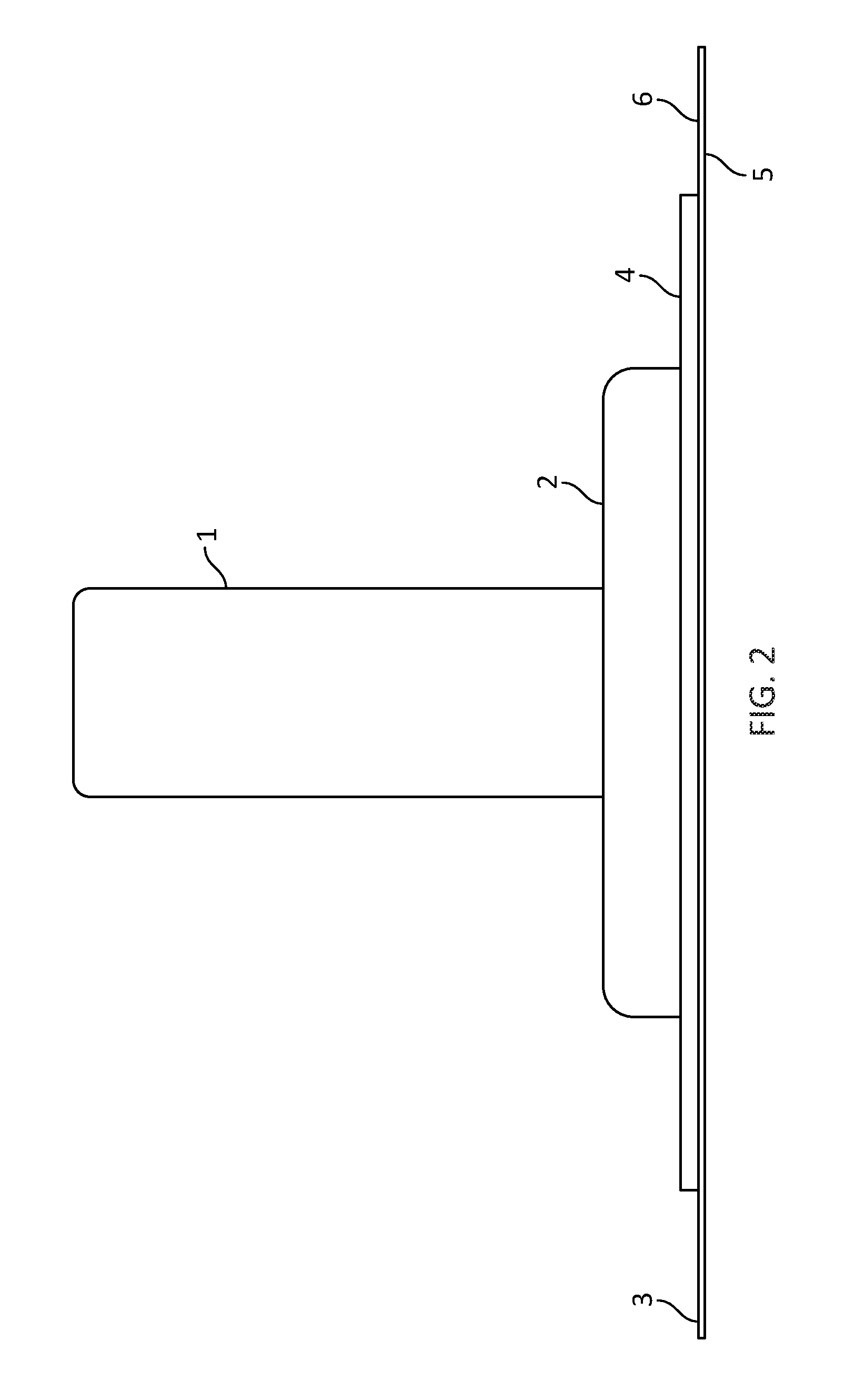
[0024]According to a compound-containing device, a hawk consists of a plate 3, cushion ring 2 and a handle 1. Plate 3 has a top surface 5 and a bottom surface 6, and handle 1 is typically centred on bottom surface 6 of plate 3. Cushion ring 2 is placed between bottom surface 6 of plate 1 and handle 5 for cushioning the worker's hand while holding the prior art hawk.

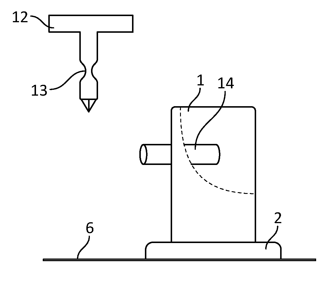
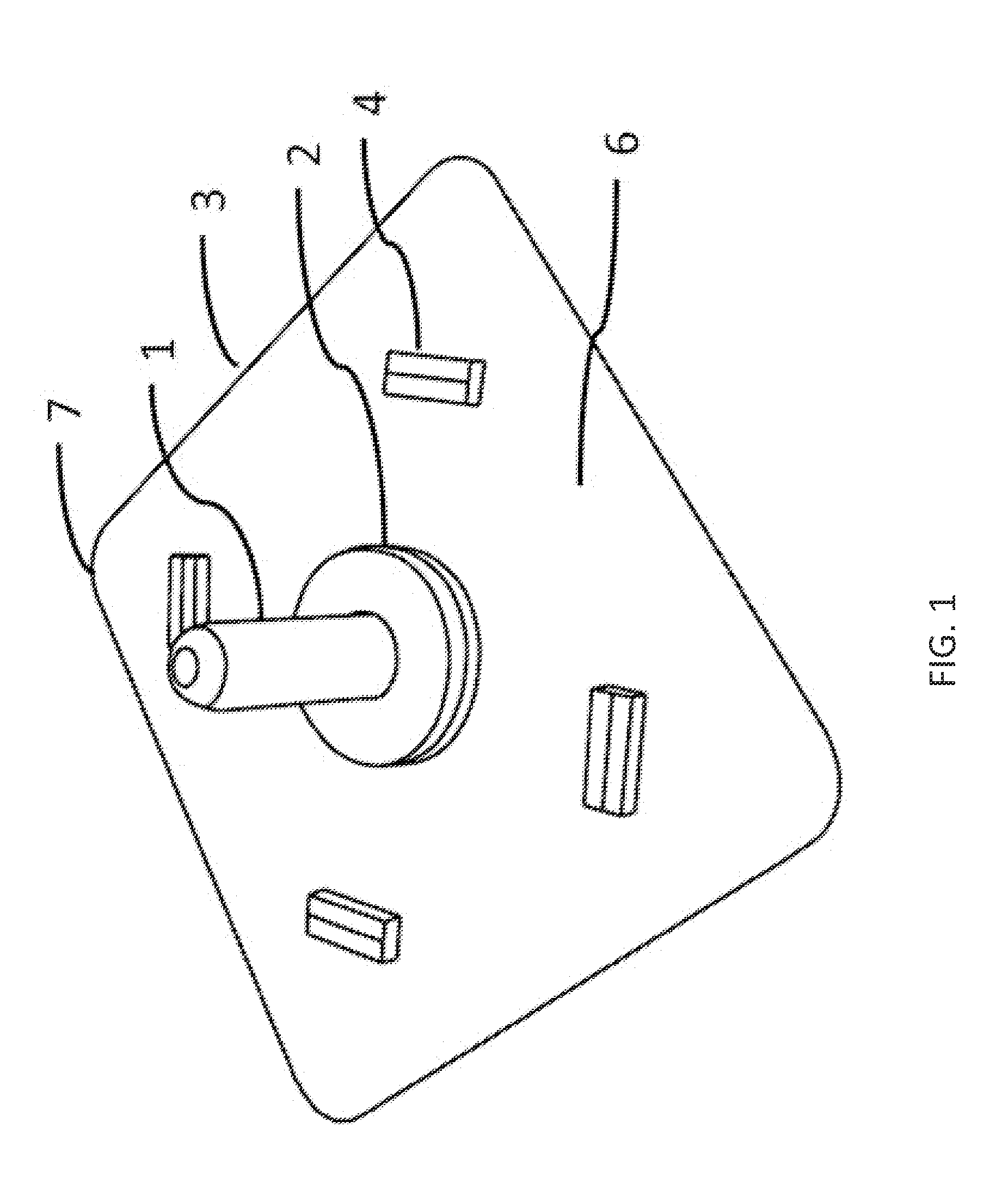
[0025]FIG. 1, FIG. 2 and FIG. 3 show an improved drywall hawk according to the invention, having retaining means for tools. FIG. 1 shows a perspective view, FIG. 2 shows an inverted elevation view, and FIG. 3 shows a bottom plan view of the hawk, which comprises plate 3 with a handle 1 placed on bottom surface 6 of plate 3. A cushion ring 2 is positioned between bottom surface 6 of plate 3 and handle 1, or mounted on bottom surface 6 of the plate 3 around handle 1, where the top of a worker's hand is likely to contact the plate 3. The plate 3 is preferably made of metal such as aluminum, however one skilled in the art wou...

second embodiment

[0031] and with reference to FIGS. 5 and 6, a pan 22 consists of a base 23, first and second ends 24, 25, and first and second sides 27, 28 all of which form sides to the base 23 and extend upwardly and outwardly from the base, such that the top edges 26 of the sides define an opening 30, which has a greater area than the area of the base 23.

[0032]One or more magnets 29 are positioned on the sides of the pan 22. The magnets 29 may be continuous around the sides of the pan 22, or may be placed in certain locations only. Preferably the magnet positions 29 allow the worker's hand to hold the pan without uncomfortable bumps from the magnets 29 impacting the hand, for example, by providing a magnet-free zone 15 for the hand to hold the pan. Examples of the magnet-free zone 15, in addition to being devoid of magnets, is rubber or silicone grips attached to the zones to aid in gripping, or indentations for the hand to facilitate a positive grip on the pan by means of the magnet-free zone. ...


PUM

PropertyMeasurementUnit
Lengthaaaaaaaaaa
Areaaaaaaaaaaa
Frictionaaaaaaaaaa

Abstract

A compound-holding device for use with a working material in one embodiment comprising a plate having a top and a bottom surface. A magnet for retaining tools is mounted on the bottom surface of the plate. In another embodiment of the invention, the handle is hollow and a magnet is placed inside the handle for retaining elongated tools such as screwdrivers within the handle. Other retaining means are threading, a clip or a locking pin system. In another embodiment a pan is disclosed having a bottom surface and sides extending upwardly and outwardly therefrom. Magnets for retaining tools are mounted on the sides of the pan for holding tools. A magnet-free zone enables holding by hand without interference of protruding magnets.

Description

CROSS-REFERENCE TO RELATED APPLICATIONS[0001]This patent application claims priority to Canadian patent application number 2,781,357 filed Jun. 28, 2012 and entitled “Compound Holding Device For Retaining Tools”. The subject matter of Canadian patent application number 2,781,357 is hereby incorporated by reference in its entirety.STATEMENT REGARDING FEDERALLY SPONSORED RESEARCH OR DEVELOPMENT[0002]Not Applicable.INCORPORATION BY REFERENCE OF MATERIAL SUBMITTED ON A COMPACT DISC[0003]Not Applicable.FIELD OF THE INVENTION[0004]The present invention relates to a compound-holding device such as a drywall hawk or pan used for holding materials for drywall and masonry applications, which retains tools for convenient access.BACKGROUND OF THE INVENTION[0005]In most constructions, ceilings and walls are made of drywall. Drywall is a plaster-like substance pressed between two sheets of thick paper. Drywall is attached to the ceiling or wall using nails and screws. The seams between the drywal...

Claims


Application Information

Patent Timeline
IPC IPC(8): E04G21/00B65D25/20
CPCE04G21/005B65D25/20B25H3/06Y10T29/49817
Inventor ZAPPIA, LORENZO
Owner ZAPPIA LORENZO
Why Eureka
Try Eureka