Shooting rest assembly

a technology of shooting rest and assembly, which is applied in the direction of weapons, weapon cleaning, and ammunition loading, can solve the problems of occupants being forced to assume awkward positions, and difficulty in manufacturing aftermarket components that attach to the guard rail, so as to reduce the risk of dropping the weapon, easy to relax, and quick and easy access to the weapon

Inactive Publication Date: 2014-01-02
DEMONIC BUCK HUNTING PROD
View PDF6 Cites 2 Cited by
  • Summary
  • Abstract
  • Description
  • Claims
  • Application Information

AI Technical Summary

Benefits of technology

The shooting rest is designed to hold a weapon upright, reducing the risk of dropping it. This allows the occupant to have their hands free for other tasks and also improves accuracy. The shooting rest is easily accessed and can be adjusted to different positions. The front and rear rests are held in a constant distance, ensuring accurate shots. This design allows for easy re-configuration and adjustment for different hunting situations.

Problems solved by technology

The varying shapes, sizes, and configurations of guard rails create difficulties in manufacturing aftermarket components that attach to the guard rails.
In any event, when a game animal approaches, the occupant must raise the weapon, which may disadvantageously attract the attention of the game animal.
Also, in some situations, the occupant can steady the weapon on the guard rail; however even in such situations, the occupant typically must assume an awkward position to do so.

Method used


Image

  • Shooting rest assembly
  • Shooting rest assembly
  • Shooting rest assembly

Examples


Embodiment Construction

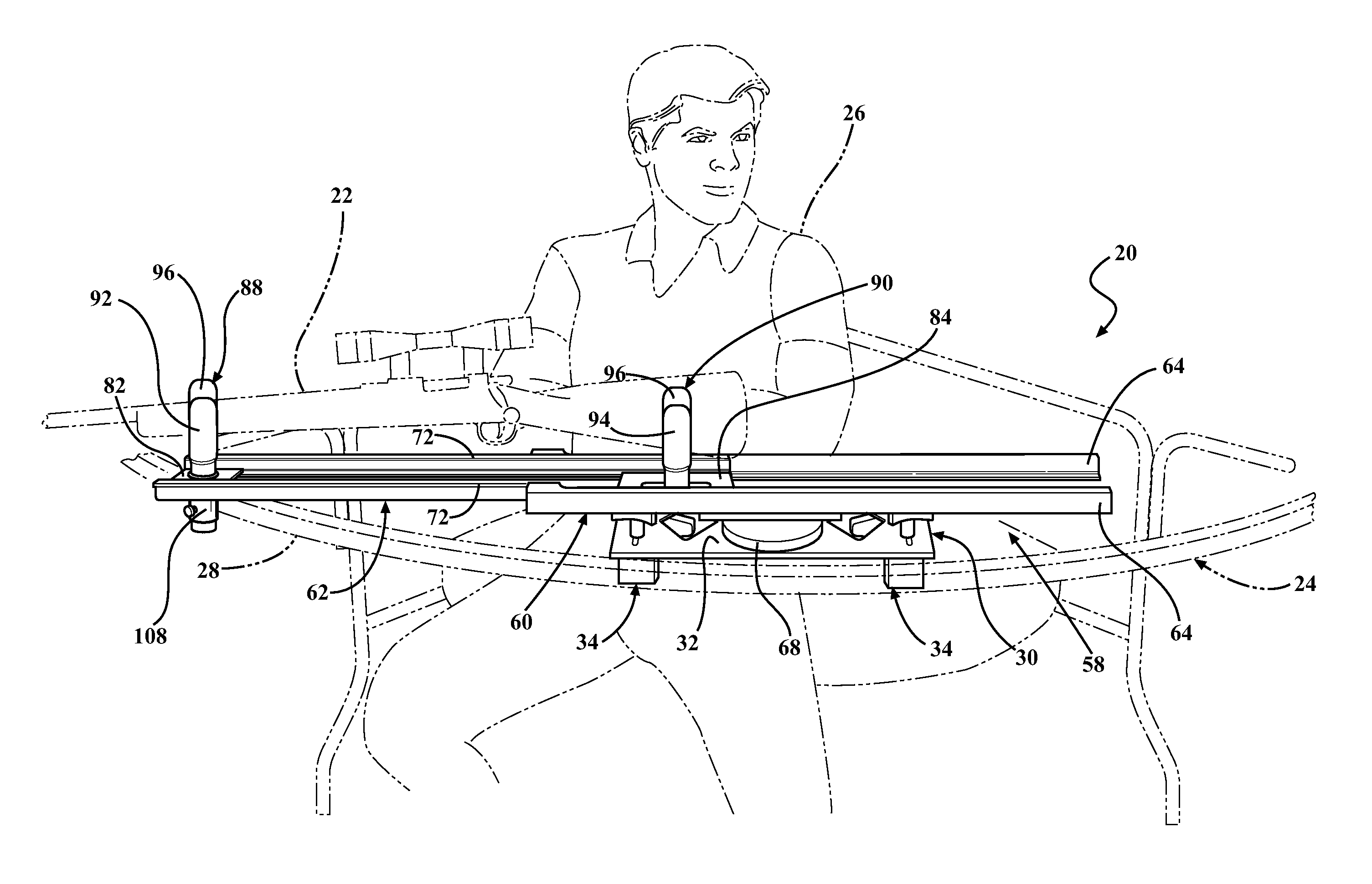
[0022]Referring to the Figures, wherein like numerals indicate like or corresponding parts throughout the several views, a shooting rest assembly 20 supports a weapon 22 on a stand 24. The stand 24 can, for example, a hunting blind. The stand 24 can be a ground stand or an elevated stand. The stand 24 is typically elevated above ground in an attempt to remove an occupant 26 from a line of sight of a game animal (not shown). However, it should be appreciated that the stand 24 can be configured to be coupled to a tripod or any other ground-level stand to support the weapon 22 for aiming at a target such as a game animal. In the case of an elevated stand, the stand 24 can be anchored to a tree and in such scenarios can be referred to in the industry as a tree stand. Alternatively, or in addition to being supported by a tree, the stand 24 can be supported by stilts. For simplicity of the Figures, the stand 24 is not shown in the tree or on the stilts.

[0023]A first embodiment of the shoo...


PUM


Abstract

A shooting rest assembly is engageable with a stand for supporting a weapon in the stand. The shooting rest assembly includes a base having at least one clamp for coupling to the stand. A platform is rotatably coupled to the base and has a platform frame and a telescoping member telescopically coupled to the platform frame. The telescoping member is configured to move along a longitudinal axis relative to the platform frame between a retracted position and an extended position. A front rest and a rear rest are spaced along the longitudinal axis and are mounted to the telescoping member in fixed positions so that each of the front rest and the rear rest move with the telescoping member as the telescoping member moves along the longitudinal axis between the retracted and extended positions relative to the longitudinal axis.

Description

RELATED APPLICATION[0001]This application claims priority to and all advantages of U.S. Provisional Patent Application No. 61 / 572,122 filed on Jul. 12, 2011, and U.S. Provisional Patent Application No. 61 / 575,977 filed on Sep. 1, 2011, both of which are incorporated herein by reference.BACKGROUND OF THE INVENTION[0002]1. Field of the Invention[0003]The subject invention generally relates to a shooting rest assembly for supporting a weapon on a stand, such as, for example, a hunting blind.[0004]2. Description of Related Art[0005]Blinds, including stands, elevated stands, etc., are used by hunters to conceal their presence from game animals. For example, elevated stands are elevated above the ground to remove the hunter from a line of sight of game animals. Elevated stands typically have a seat and / or a foot rest to support the occupant of the elevated stand. Some elevated stands have one or more guard rails that extend at least partially around the occupant to assist in retaining the...

Claims


Application Information

Patent Timeline
Patent Type & Authority Applications(United States)
IPC IPC(8): F41A23/18
CPCF41A23/18F41A23/02
Inventor BASTIAN, JR., DAVID B.
Owner DEMONIC BUCK HUNTING PROD
Why Eureka
Try Eureka