Micro reservoir, particularly for integration in a microfluidic flow cell

a micro reservoir and flow cell technology, applied in the field of micro reservoirs, can solve the problems of fluid shooting out of the storage space at a high flow rate, affecting the flow rate of fluid, so as to facilitate the controlled and dosed removal of stored fluid

Active Publication Date: 2014-01-02
THINXXS MICROTECHNOLOGY AG
View PDF11 Cites 24 Cited by
  • Summary
  • Abstract
  • Description
  • Claims
  • Application Information

AI Technical Summary

Benefits of technology

[0007]The invention is based on the object to provide a novel micro reservoir of the above ment

Problems solved by technology

For opening the storage space, the storage space is pressed together with a deformation of the foil until such a pressure is built up at the lock provided as an intended breaking point, causing a rupture of the intended breaking point.
Disadvantageously, the fluid pressure required for eliminating the lock causes the fluid to shoot out of the storage space at a high flow speed in the first moment after opening the outlet duct.
A partial quantit

Method used


Image

  • Micro reservoir, particularly for integration in a microfluidic flow cell
  • Micro reservoir, particularly for integration in a microfluidic flow cell
  • Micro reservoir, particularly for integration in a microfluidic flow cell

Examples


Embodiment Construction

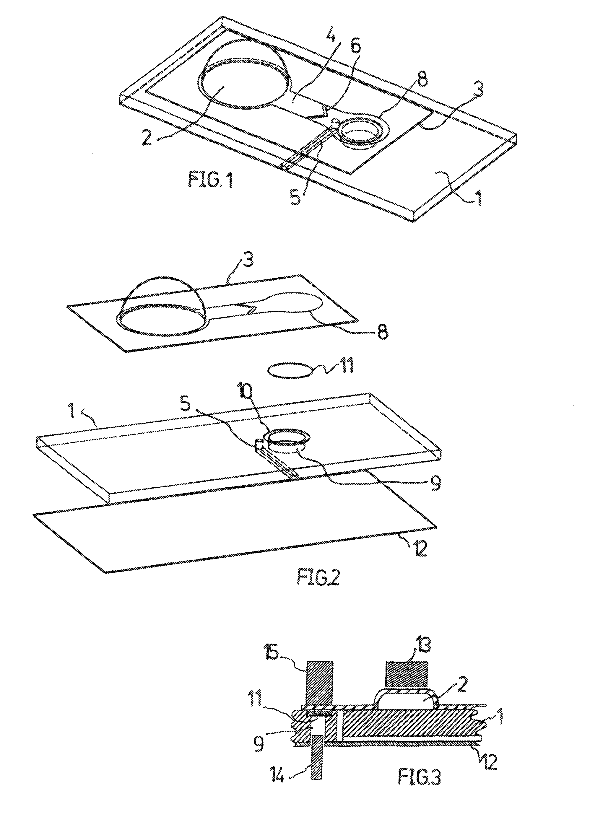
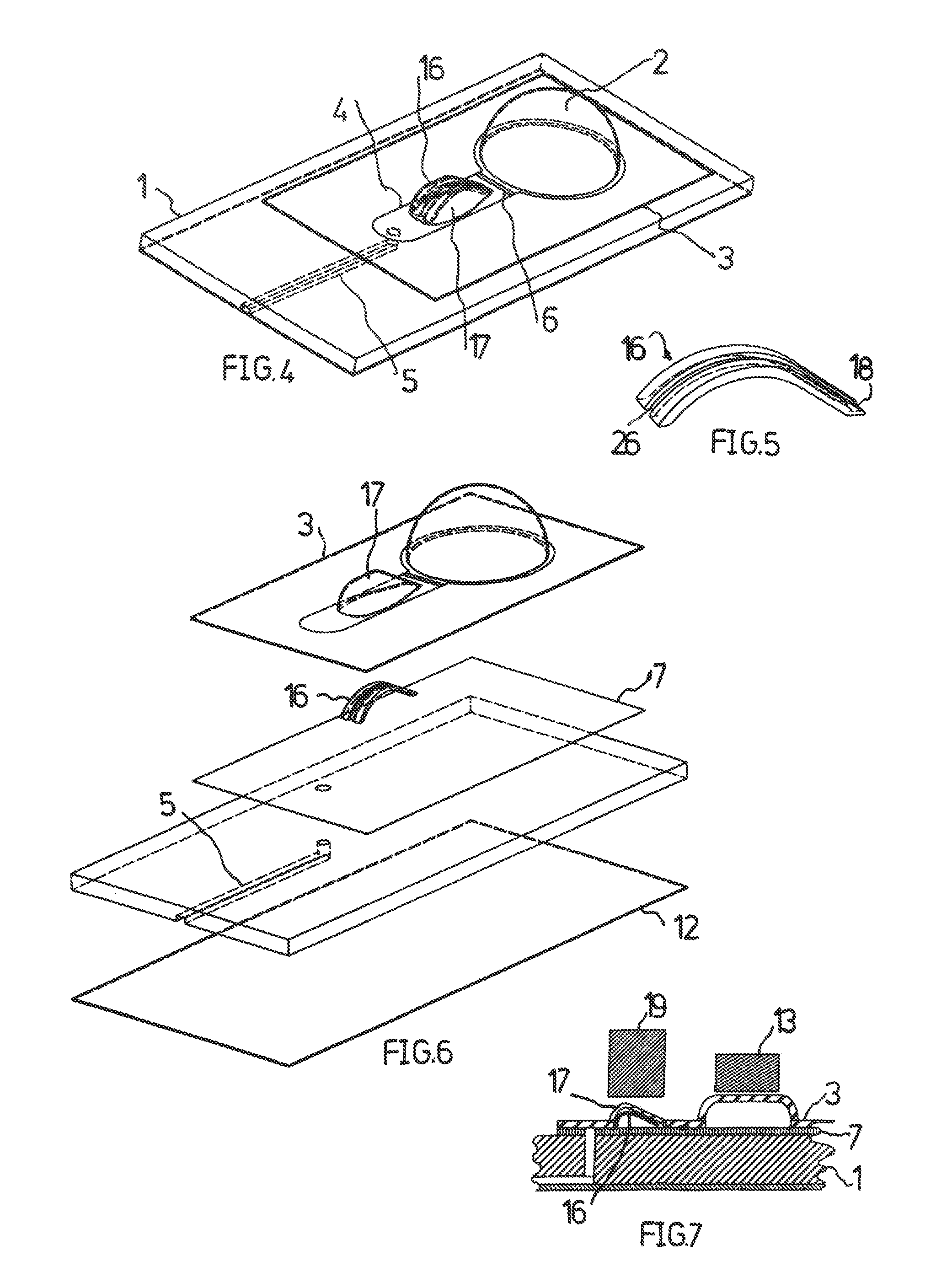
[0039]Initially, reference is made to FIG. 12 wherein, in partial Figures (a) through (f), conventional micro reservoirs are shown in which a microfluidic flow cell is integrated with a substrate 1. Preferably, the substrate is composed of a synthetic material and is manufactured by injection molding.

[0040]In accordance with the examples (a) through (d), a storage space 2 for a fluid is formed between the substrate 1 and a foil 3 welded or / and glued to the substrate by an indentation in the foil (FIG. 12a) or in the substrate (FIGS. 12b through d).

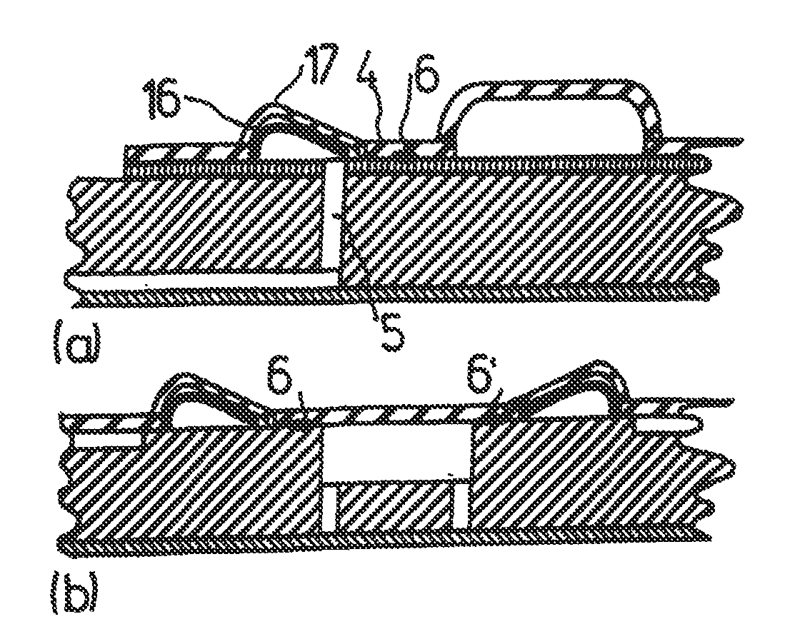
[0041]An outlet duct 4 connected to the storage space 2, which ends at a duct 5 leading through the substrate 1, is formed by not connecting the foil 3 to the substrate 1 in the area of the duct 4.

[0042]A lock 6 is formed for the fluid in the storage space 2 through which the storage space 2 is hermetically sealed by welding or / and gluing the foil 3 to the substrate 1 in an area traversing the duct 4.

[0043]In the example of FIG. 12d, two o...


PUM


Abstract

A micro reservoir, particularly for integration in a microfluidic flow cell, with a storage space for receiving a fluid and being in connection with an outlet duct for the fluid, wherein a cancelable lock for the fluid is formed. A mechanism is provided for canceling the lock without pressure of the fluid acting on the lock. The mechanism preferably mechanically destroys the lock.

Description

CROSS-REFERENCE TO RELATED APPLICATIONS[0001]The present application claims priority of EP 12 173 976.7, filed Jun. 28, 2012, the priority of this application is hereby claimed and this application is incorporated herein by reference.BACKGROUND OF THE INVENTION[0002]The invention relates to a micro reservoir, particularly for integration in a microfluidic flow cell, with a storage space containing a fluid, wherein the storage space is in communication with an outlet duct for the fluid in which a cancelable lock for the fluid is formed.[0003]Micro reservoirs of this type are known from WO2009 / 071078 A1. The storage space and the outlet duct of this known micro reservoir are formed by two foils arranged on a plate-shaped substrate, wherein the foils are welded or / and glued together so as to define the storage space and the outlet duct. For forming the storage space, the foil facing away from the substrate has a spherically shaped deformation. A welded or / and glued connection of the fo...

Claims


Application Information

Patent Timeline
IPC IPC(8): B01L3/00
CPCB01L3/50B01L3/50273B01L2300/123B01L3/5027B01L2300/0809Y10T137/8593
Inventor WEBER, LUTZNEUMEIER, MICHELKECK, STEFAN
Owner THINXXS MICROTECHNOLOGY AG
Why Eureka
Try Eureka