Power operated chuck

Active Publication Date: 2014-01-02
SMW AUTOBLOK SPANNSYST GMBH
View PDF21 Cites 12 Cited by
  • Summary
  • Abstract
  • Description
  • Claims
  • Application Information

AI Technical Summary

Benefits of technology

[0020]It is particularly advantageous if the actuating pin is mounted in a stabilisation sleeve in such a way as to be partially movable in relation to that stabilisation sleeve, for the stabilisation sleeve to be supported on the inner wall of the guide hole, and for part of the movement of the actuating pin to take place up to a specified stop before being stopped, as a result of which a relative movement takes place between the actuating pin and the stabilisation sleeve. This is because the stabilisation sleeve a

Problems solved by technology

Often, however, this centring force is much too large in magnitude, a

Method used


Image

  • Power operated chuck
  • Power operated chuck
  • Power operated chuck

Examples


Embodiment Construction

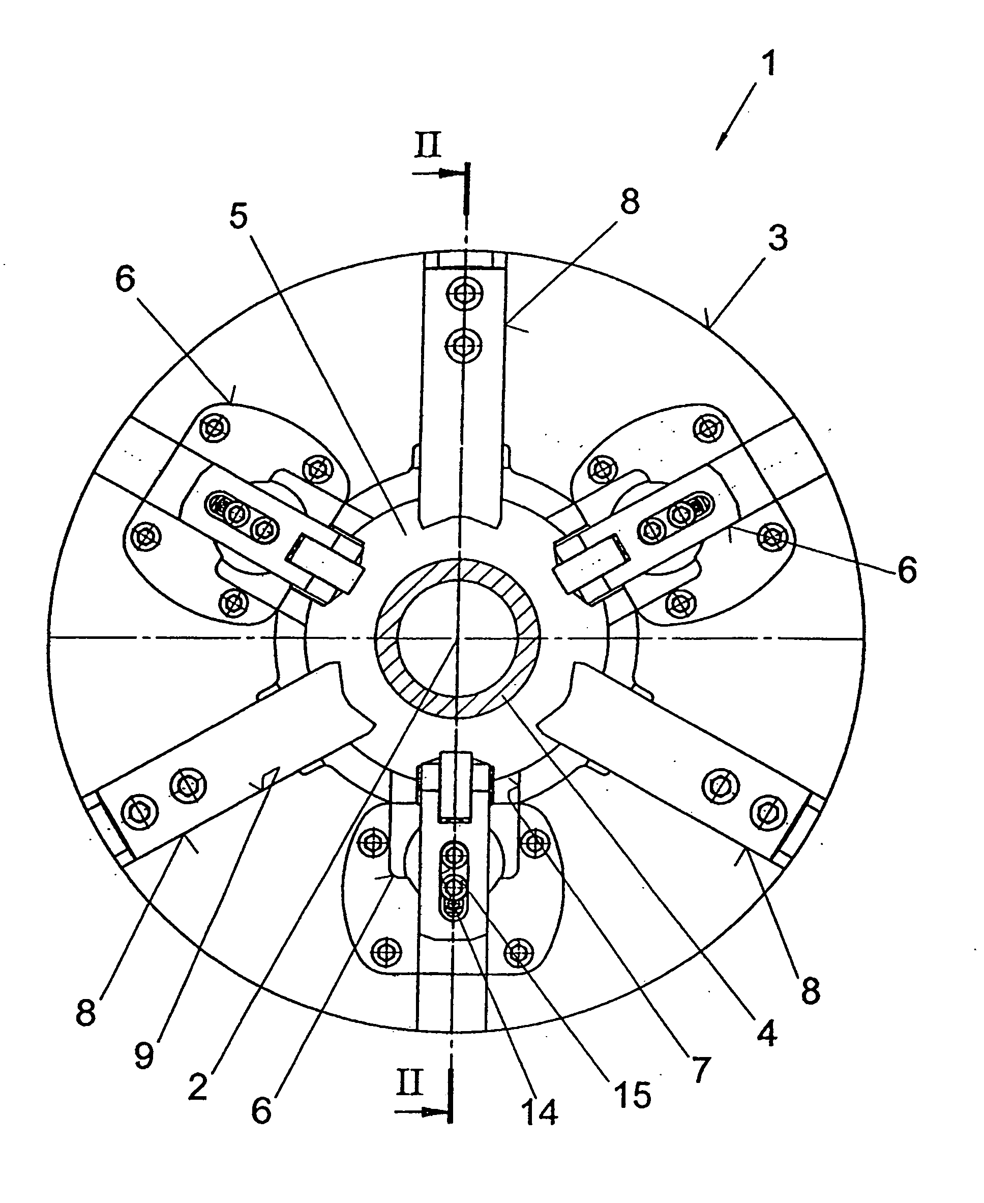
[0034]FIG. 1 shows a power-operated chuck 1 by means of which cylindrically shaped workpieces 4 are supported while being machined by a machine tool. A passage hole 5 is worked into a chuck body 3 of the power-operated chuck 1 in order to hold the particular workpiece 4, the centre of which passage hole 5 runs in alignment with a lengthways axis 2 of the power-operated chuck 1 and / or the chuck body 3. The workpiece 4 should be provided with a male or a female thread, in particular on its free ends.

[0035]It is necessary to position the workpiece 4 initially in a central position in relation to the lengthways axis 2 of the chuck body 3 in order to achieve machining of the workpiece 4 without defects. For this purpose, the chuck body 3 is provided with three centring jaws 6 inserted in it, each of which is mounted in a radially movable arrangement in a guide groove 7 worked into the chuck body 3. As soon as the centred position of the workpiece 4 is achieved by the advance movement of ...


PUM

PropertyMeasurementUnit
Lengthaaaaaaaaaa
Forceaaaaaaaaaa
Distanceaaaaaaaaaa

Abstract

A chuck assembly for supporting cylindrically shaped workpieces to be machined at their ends, the assembly comprising
    • a body having a passage in its lengthways axis,
    • a driving for providing an actuation force absorbed by an actuating pin axially movable in the body,
    • a guide hole in the body having the actuating pin therein, and
    • centring jaws, mounted in a guide groove in the chuck body and moveable radially toward the workpiece, each in a driving arrangement an actuating pin.
A roller provided on the driving means facing the actuating pin, a contact surface is on a free end of the pin at right angles to the lengthways axis of the chuck body. The contact surface and the roller interacting such that forces of driving means transfer onto the contact surface axially, and simultaneously a movement at right angles to the lengthways axis of the chuck body is released between the contact surface of the actuating pin and the roller.

Description

BACKGROUND OF THE INVENTION[0001]1. Field of the Invention[0002]The present invention relates to a power-operated chuck for supporting cylindrically shaped workpieces which are to be machined by means of a machine tool in the area of their free ends.[0003]2. Description of the Prior Art[0004]Power-operated chucks of this kind have been produced successfully by the Applicant for decades under the identification Big Bore® and placed on the market. These power-operated chucks have a passage opening extending in the lengthways axis of the power-operated chuck, in order to accommodate a workpiece to be machined.[0005]In order to position the cylindrically shaped workpiece as exactly centrally as possible in relation to the lengthways axis of the chuck, the chuck body of the chuck is provided with three centring jaws arranged at 120° intervals from one another in the circumferential direction of the workpiece, and which are advanced synchronously by means of a drive piston in the directio...

Claims


Application Information

Patent Timeline
IPC IPC(8): B23B31/16
CPCB23B31/16287B23B31/1627B23B31/1253B23B31/1215B23B31/1223B23B31/16B23B2215/72B23B2231/22B23B2260/008B23B2260/0082B23B2260/026B23B2260/116B23B2270/12Y10T279/1224Y10T279/1241Y10T279/17666
Inventor HELM, PETERDEININGER, HARALD
Owner SMW AUTOBLOK SPANNSYST GMBH
Why Eureka
Try Eureka