Motor

a brushless, motor technology, applied in the direction of dynamo-electric machines, electrical equipment, supports/enclosements/casings, etc., can solve the problems of excessive processing time and miniaturization of motors, and achieve the effect of reducing the height of motors and improving the productivity of motor assembly

Active Publication Date: 2014-01-02
LG INNOTEK CO LTD
View PDF11 Cites 5 Cited by
  • Summary
  • Abstract
  • Description
  • Claims
  • Application Information

AI Technical Summary

Benefits of technology

[0036]There is an advantageous effect in the motor according to an exemplary embodiment of the present disclosure in that a motor height can be reduced to provide a further miniaturized motor, because each polarity and common terminal connections of electric power can be enabled by stacking a plurality of plate members instead of the conventionally used complicated structure of busbar.
[0037]Another advantageous effect is that productivity of motor assembly can be improved by replacing the complicated process of connecting a distal ends of coils wound on a stator to a terminal of busbar with a process of inserting the distal ends of coils into a plate member, and heating and soldering using a heating gun.

Problems solved by technology

However, there is a disadvantage in a connecting process of a busbar to a coil, in a case the busbar is used to connect the coil, and in miniaturizing a motor because a height of an EPS motor increases as high as a height of the busbar.
Another disadvantage is that a processing time is excessively required to manufacture a busbar, because of a complicated process such as mold-formation of a busbar body using an insulator by formation of a busbar.

Method used


Image

  • Motor
  • Motor
  • Motor

Examples


Embodiment Construction

[0046]Now, a motor according to the exemplary embodiment of the present disclosure will be described in detail with reference to the accompanying drawings.

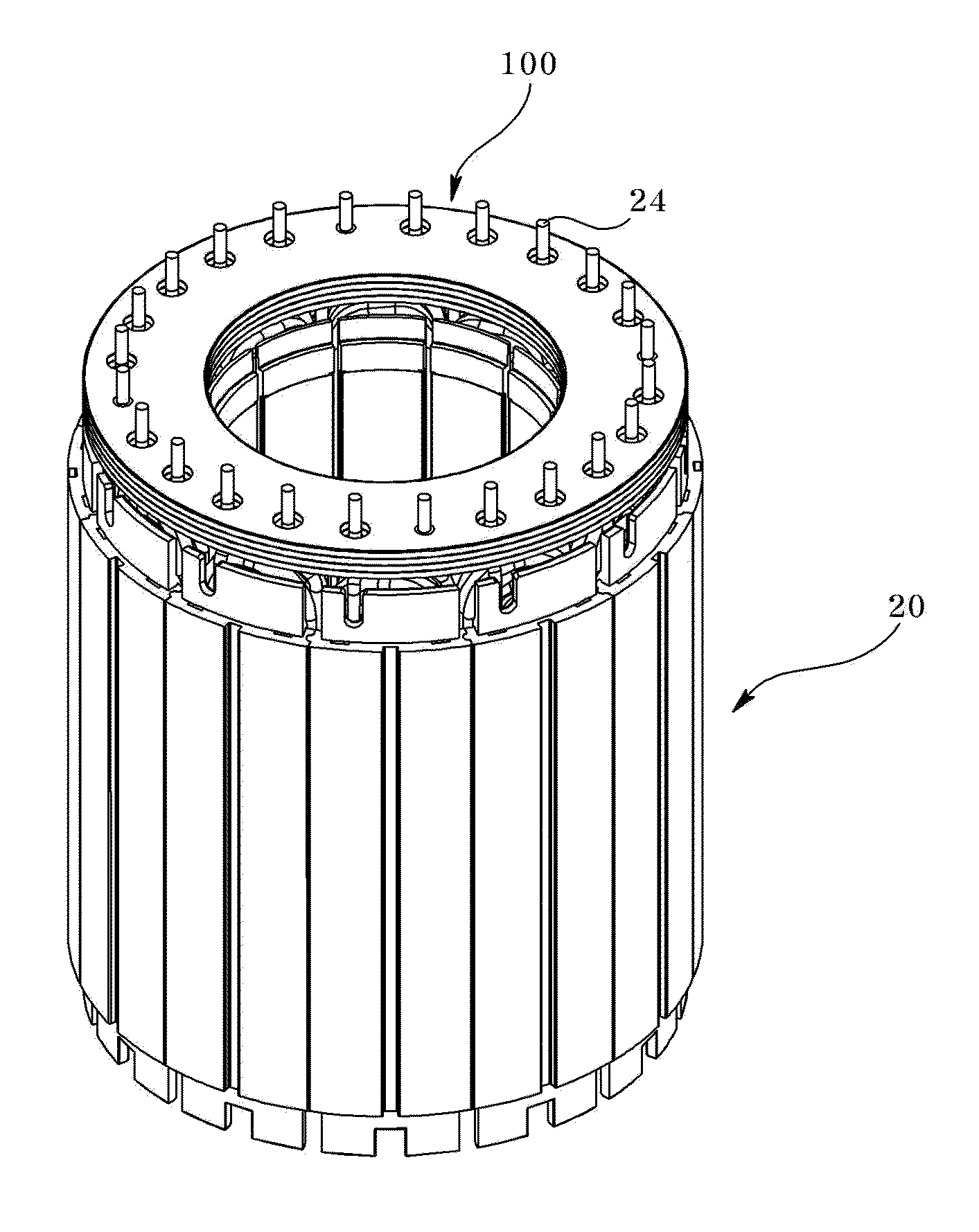
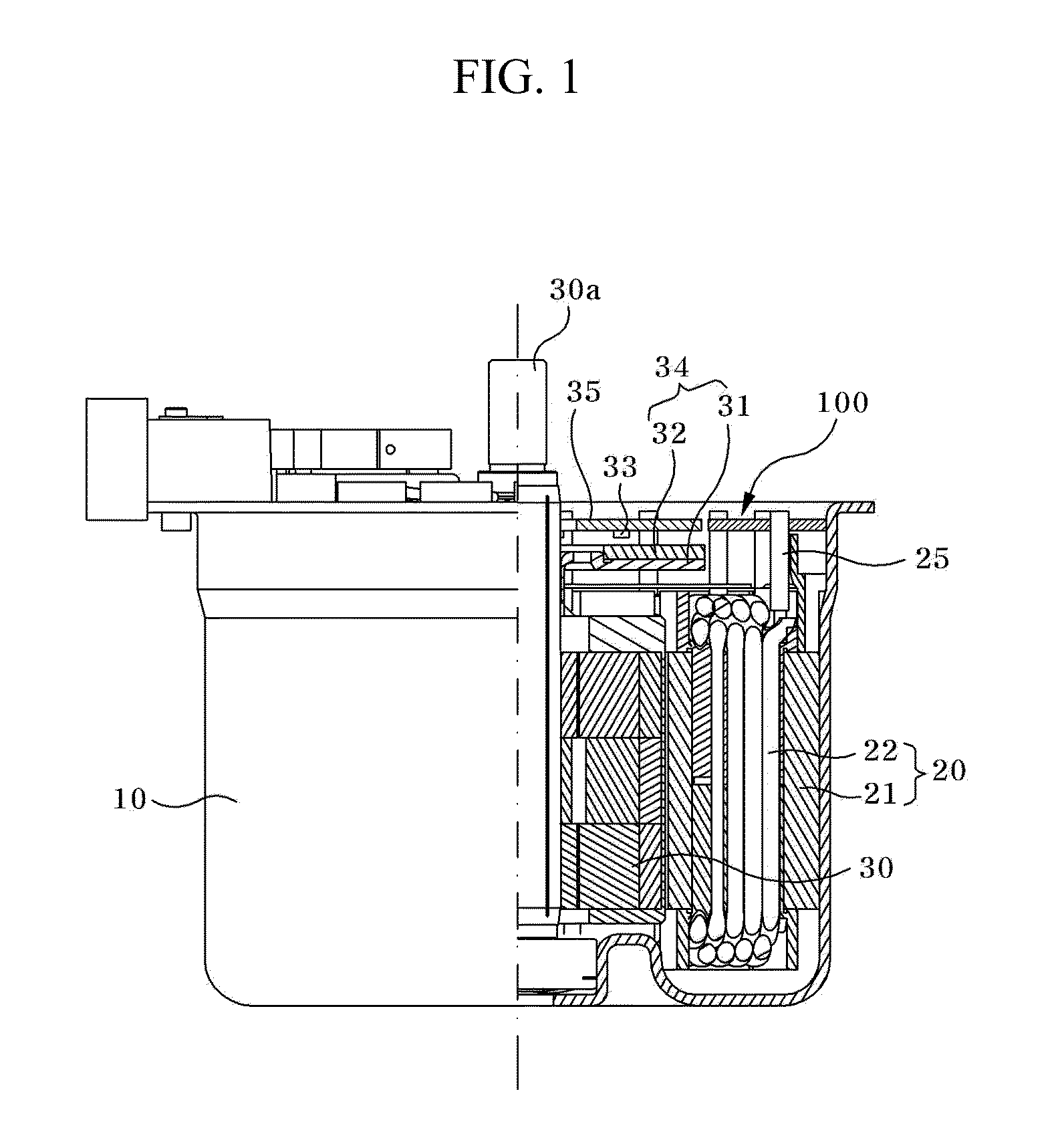
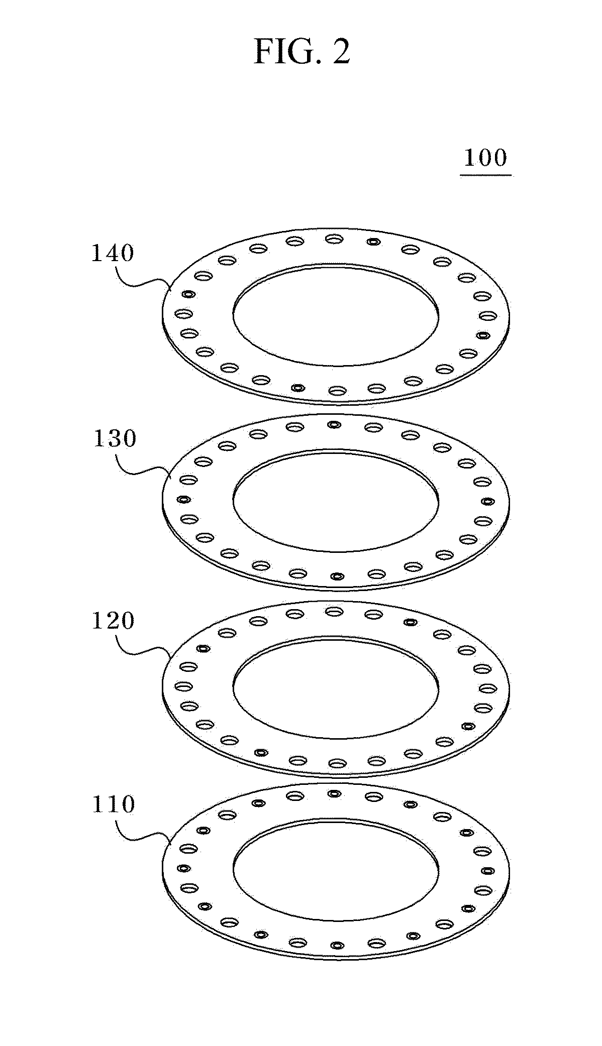
[0047]FIG. 1 is a partially cut-out cross-sectional view illustrating a motor according to an exemplary embodiment of the present disclosure, FIG. 2 is an exploded perspective view illustrating a plate module according to an exemplary embodiment of the present disclosure, FIG. 3 is a plan view illustrating a first plate of FIG. 2, FIGS. 4 to 6 are plan views illustrating second to fourth plates of FIG. 2, FIG. 7 is a perspective view illustrating a stator core wound with a coil, FIG. 8 is a perspective view illustrating a state in which a distal end of a coil wound on a stator core of FIG. 7 is stripped and a plate module inserted into, FIG. 9 is a perspective view illustrating a state in which a stripped portion of the coil protruded to an upper surface of the plate module of FIG. 8 is cut out, and FIG. 10 is a perspective view i...


PUM


Abstract

A motor is provided, the motor including a motor housing, a stator mounted inside the motor housing and including a stator core and a coil wound on the stator core, a rotor rotatably installed at a center of the stator, and a plate module stacked with a plurality of plates, and coupled to the stator and to an upper surface of a rotor to supply an electric power to the coil.

Description

CROSS-REFERENCE TO RELATED APPLICATION[0001]This application claims the benefit under 35 U.S.C. §119 of Korean Patent Application No. 10-2012-0069847, filed Jun. 28, 2012, which is hereby incorporated by reference in its entirety.BACKGROUND[0002]1. Field of the Disclosure The present disclosure relates to a brushless motor.[0003]2. Discussion of the Related Art[0004]Generally, almost every vehicle employs an electric power-assist steering system. Such an electric power-assist steering system generates an assist force based on the steering torque and the steering angle in order to enhance the steering performance of the vehicle.[0005]That is, a steering system that assists a steering force of a vehicle with a separate power is used to enhance the motion stability of a vehicle. Conventionally, the auxiliary steering device uses hydraulic pressure, but an Electronic[0006]Power Steering (EPS) system adapted to transmit a rotation output of an electric motor to a steering shaft via a spe...

Claims


Application Information

Patent Timeline
Patent Type & Authority Applications(United States)
IPC IPC(8): H02K11/00
CPCH02K11/0094H02K3/522H02K2203/03H02K29/00H02K5/22H02K11/00
Inventor RYU, WOONGSEON
Owner LG INNOTEK CO LTD
Why Eureka
Try Eureka